
CloudFS Version 8.7.1.0
Table of Contents
- Overview ..... 6 1.1 Panzura Node Family ..... 6 1.2 Cloud Storage Tier Options ..... 6 1.3 Configuring the node ..... 12
- Deploying a Panzura CloudFS Cluster ..... 13 2.1 Planning a Deployment ..... 13 2.2 Deploying Panzura CloudFS ..... 13
- Panzura Architecture ..... 17 3.1 Master and Subordinate Nodes ..... 17 3.2 Configuration Replication ..... 17 3.3 Local and Remote nodes ..... 18 3.4 Node Features ..... 18
- Clustered Deployments ..... 20 4.1 Sample Deployment ..... 20
- What's New? ..... 21 5.1 Grafana Cloud Integration ..... 21 5.2 Quarter-Hourly Scheduled Snapshots ..... 21 5.3 Node Decommission and Activation/Deactivation Enhancements ..... 21 5.4 Third-Party Multi-Consumer Audit Streaming ..... 21 5.5 Prewarm Provision updates ..... 22 5.6 Local HA Failover Improvements ..... 22 5.7 Ring Health Check Report ..... 22
- Key Features and enhancements ..... 23 6.1 Prewarm Provision ..... 23 6.2 Health Check Diagnostics ..... 23 6.3 File Lock Release ..... 23 6.4 Adaptive Snapshot Retention (aka Setting up Snapshots) ..... 23 6.5 Ring Status Management ..... 23 6.6 Regional Store v2 ..... 23 6.7 Enhancements in Grafana dashboard ..... 24 6.8 Storage Class Tier Support in CloudFS ..... 24 6.9 Quota Management ..... 24 6.10 Geofencing Policy ..... 24 6.11 S3 Interface ..... 24 6.12 Time-Series Statistics ..... 24
6.13 Manage Share Access ..... 25 6.14 Support for Role-Based Access Control (RBAC) for System Management ..... 25 6.15 Audit Trail ..... 25 6.16 CloudFS Instant Node ..... 25 6.17 User Auto Scaling ..... 25 6.18 Enhanced regional store ..... 25 6.19 Enhanced Node Decommissioning ..... 25 6.20 Extended RBAC support for OKTA Identity Provider using SAML & OIDC Protocols ..... 26 6.21 UX Dashboard and PZIQ Settings ..... 26 6.22 VM Support for Linux KVM (RHEL 9.4+) ..... 26 6.23 Panzura Global Namespace ..... 26 6.24 Cloud Mirroring ..... 26 6.25 File Locking ..... 27 6.26 Snapshots ..... 28 6.27 Smart Cache ..... 28 6.28 Extended File System ACLs ..... 28 6.29 Scale out Global Deduplication ..... 28 6.30 Enhanced Cloud Diagnostics ..... 28 6.31 Intelligent Symantec NetBackup Integration ..... 28 6.32 High Availability Solution ..... 29 6.33 DR Cloud Recovery ..... 29 6.34 Enterprise AntiVirus Plugin ..... 29 6.35 FIPS ..... 29 7. CloudFS Instant Node ..... 30 7.1 Restore A Node (Recovering a node) ..... 30 7.2 Commission a New Node ..... 33 7.3 Restore VMware virtual machine Hypervisor snapshots ..... 34 8. Panzura Quick Start Guide ..... 38 8.1 Web Browser Requirement ..... 38 8.2 Deployment Mode: One-arm or Inline ..... 38 8.3 Pre-installation Checklist ..... 38 8.4 Site Preparation ..... 40 8.5 Cloud Storage Provider Requirements ..... 42 8.6 Finding the node IP Address ..... 42 8.7 Changing the node IP Address (using the CLI) ..... 42 9. Setting Up the Panzura Node ..... 44 9.1 Node Information ..... 44 9.2 Cloud Provider Information ..... 46
9.3 Bringing Up a Node for the First Time ..... 48 9.4 Accessing the Setup Wizard ..... 49 9.5 Configuration Wizard ..... 49 10. Using the CloudFS Dashboard ..... 50 10.1 Default Dashboard ..... 50 10.2 Manage Dashboards ..... 58 10.3 Adjust the Date Range ..... 58 10.4 Dashboard Explorer ..... 58 11. Using the Panzura CloudFS User Interface ..... 59 11.1 Overview ..... 59 11.2 About CloudFS Map ..... 59 11.3 Using the CloudFS UI ..... 60 12. Configuration ..... 65 12.1 System Settings ..... 65 12.2 Network Settings ..... 68 12.3 Monitoring ..... 78 12.4 Encryption Settings ..... 99 12.5 CloudFS Settings ..... 104 12.6 NFS/SMB Mixed Mode ..... 114 12.7 NFS Settings ..... 116 12.8 Setting up Snapshots ..... 119 12.9 Setting Up Smart Cache ..... 122 12.10 High Availability Settings ..... 126 12.11 Default Auto Prepopulate/Prefetching Features ..... 132 12.12 Active Directory ..... 133 12.13 License Manager ..... 135 12.14 Disk Expansion ..... 151 12.15 Access Control ..... 151 12.16 Geofencing Policy ..... 178 12.17 Quota Management ..... 182 13. Maintenance ..... 186 13.1 Diagnostic Tools ..... 186 13.2 System Operations ..... 193 13.3 ICAP Operations ..... 194 13.4 ICAP Operations ..... 196 13.5 CloudFS Operations ..... 196 13.6 SMB/NFS Operations ..... 198 13.7 System Reset and Cleanup ..... 201
13.8 Master Node Operations ..... 202 14. Notifications Center ..... 216 14.1 Alerts ..... 216 14.2 Audit Trail ..... 216 14.3 View Running Processes ..... 219 15. Panzura Application Programming Interface ..... 220 15.1 Accessing API Syntax Information ..... 220 15.2 API Authentication and Authorization ..... 220 15.3 Web UI API Console ..... 220 15.4 Accessing API Syntax Information ..... 220 15.5 Statistics Collection System ..... 221 15.6 RestAPIs for S3 Interface ..... 224 15.7 Rest APIs for Audit Trail ..... 228 15.8 Rest APIs for Quota Management ..... 230 15.9 Rest APIs for Prewarm Provision ..... 232 15.10 Rest APIs for Geofencing Policy ..... 235 16. CloudFS and Azure AD ..... 238 16.1 Microsoft Azure Active Directory Domain Services (AD DS) ..... 238 16.2 Comparing Active Directory to Azure Active Directory ..... 238 16.3 Leveraging Azure AD for Multi-factor Authentication with Panzura CloudFS ..... 240 17. Additional Information ..... 241 17.1 Windows Users and Files that Are Slow to Open ..... 241 17.2 Updating AWS Credentials on Panzura Nodes ..... 241 17.3 Creating a Microsoft Azure Storage Container ..... 243 17.4 Creating a Vault or Container in the IBM Cloud Object Store ..... 244 17.5 File Access Auditing Support for SMB and NFS Clients ..... 245 17.6 ICAP Best Practices ..... 247 17.7 Revit Best Practices ..... 248
1. Overview
This guide is designed to help administrators effectively manage and optimize the CloudFS environment. CloudFS is a hybrid cloud file services platform that consolidates data storage, enhances collaboration, and ensures data security and resilience. By integrating various storage solutions into a unified system, CloudFS simplifies data management and reduces operational complexity. It provides robust features such as global file synchronization, real-time collaboration, and advanced security measures like encryption and ransomware protection.
Additionally, this guide describes the CloudFS node, which is a critical component of the CloudFS architecture. The CloudFS node acts as a bridge between local storage and cloud storage, enabling seamless data transfer and synchronization. The guide covers detailed instructions on how to deploy and manage CloudFS nodes, including initial setup, configuration, and ongoing maintenance. Administrators will learn best practices for optimizing node performance, ensuring high availability, and troubleshooting common issues to maintain a resilient and efficient CloudFS environment.
1.1 Panzura Node Family
Panzura CloudFS enables organizations to solve growing unstructured data challenges by combining data center performance with the economics, scalability, and durability of cloud storage.
CloudFS delivers unprecedented performance and scale, expanded data center workloads, deployment on any platform and any cloud, automated, centralized management, and unmatched cloud data protection.
- CloudFS Archive: Replaces expensive single site NAS systems with a hybrid cloud storage platform that combines data center performance with the economics, scalability, and durability of the cloud. Archive can replace your entire backup and archive infrastructure with a more resilient, automated solution. It provides business continuity because it appears to users like a local network drive while storing all unstructured data in the cloud. Local performance is provided by high-performance flash and advanced caching algorithms that ensure that every application has the data it needs when it is needed.
- CloudFS NAS: Empowers organizations to break free from the storage status quo and eliminate islands of storage by consolidating their unstructured data to the cloud. Expensive, traditional NAS storage can be eliminated by centralizing unstructured data in the cloud, while keeping active data cached close to users. This modern cloud plus cache model is simpler, faster, and less expensive than deploying traditional primary, backup, and archive storage at each site.
- CloudFS Collaboration: Enables real-time collaboration across the enterprise by consolidating unstructured data to the cloud. Collaboration looks and behaves just like a local, locking NAS or Windows node to users, but is backed by a central cloud data repository and can span hundreds of sites. Byte-range locking, combined with immediate global consistency enables globally distributed users to work together as if they are in the same room. It's simpler, faster, and less expensive than deploying primary, backup, and archive storage at each site, and running WAN optimization over private networks.
1.2 Cloud Storage Tier Options
The following object storage services and products have been validated to work as object storage for Panzura CloudFS. Note: For Panzura CloudFS 7, Data download (per GB) cost may be more than Tiered Cost Savings. Please, check with your Account Manager for more details.
| Object Storage | Cloud Storage Tier | Panzura Support Availability | Description |
|---|---|---|---|
| Amazon S3 | S3 Standard | YES | S3 Standard offers high durability, availability, and performance object storage for frequently accessed data. Because it delivers low latency and high throughput, S3 Standard is appropriate for a wide variety of use cases, including cloud applications, dynamic websites, content distribution, mobile and gaming applications, and big data analytics. |
| S3 Standard-Infrequent Access | YES* | S3 Standard-IA is for data that is accessed less frequently but |
| S3 Intelligent Tiering | YES | requires rapid access when needed. S3 Standard-IA offers the high durability, high throughput, and low latency of S3 Standard with a low per GB storage price and per GB retrieval fee. This combination of low cost and high performance makes S3 Standard-IA ideal for long-term storage, backups, and as a data store for disaster recovery files. | |
| S3 One Zone-Infrequent Access | YES* | S3 Intelligent-Tiering is an Amazon S3 storage class designed for customers who want to optimize storage costs automatically when data access patterns change, without performance impact or operational overhead. | |
| Glacier | NO | S3 Glacier Storage Class is intended for long-term storage Archive that is not meant to be accessed quickly. | |
| Google Cloud Storage | Multi-Region | YES | Google Cloud Storage MultiRegional stores data in data centers across the globe and has 99.95% availability. It is suitable for companies that need to access data frequently, such as for website content and mobile application data. Multi-Regional class data is stored in at least two separate locations, which improves availability. |
| Regional Storage | YES |
| Nearline Storage | YES* | Google Cloud Storage Nearline is for customers who need longterm storage for data that users access less than once a month. It's best used for archiving data, backup, and disaster recovery (DR). Ideal for back-up and serving long-tail multimedia content. | |
| Coldline Storage | YES* | Google Cloud Storage Coldline is for customers who need to store data they access less than once a year. It is mainly for archiving and DR. It requires a 90-day minimum storage duration and is the least expensive of the three storage tiers. Typically, this is for disaster recovery or data that is archived and might or might not be needed in the future | |
| Azure Storage | Hot | YES | Optimized for storing data that is accessed frequently. Hot Blob Storage tier offers 99.9% availability with latency in milliseconds with general purpose version 1 and 2 account type. |
| Cool | YES* | Optimized for storing data that is infrequently accessed and stored for at least 30 days. Cool Blob Storage tier offers 99.9% availability with latency in milliseconds with general purpose version 2 account type only. | |
| Archive | NO | Optimized for storing data that is rarely accessed and stored for at least 180 days with flexible latency requirements (on the order of hours). | |
| IBM Public Cloud | Standard | YES | The Standard storage tier is used for active workloads that require high performance and low |
| latency, and data needs to be frequently accessed (multiple times a month). There is no charge for data retrieval besides the cost of the operational request and public outbound bandwidth. Common use cases include streaming mobile and web content, DevOps, analytics, collaboration, and active content repositories. | ||
|---|---|---|
| Vault | YES* | The Vault storage tier is used for less active workloads that require infrequent data access (accessed once a month or less), but require immediate, real-time access when needed. A low retrieval charge applies when reading data. Vault offers the same high durability, high throughput, and low latency of the Standard class tier. Vault includes a threshold for object size and storage period that's consistent with the intended use of this service for cooler, less active data. Common use cases include backup and digital asset retention. |
| Cold Vault | YES* | The Cold Vault storage class tier is used for cold workloads where data is primarily archived (accessed a few times a year) but requires immediate, real-time access when needed. A larger retrieval charge applies for reading data. Cold Vault includes a threshold for object size and storage period that's consistent with the intended use of this service to store cold, inactive data. Common use cases include long-term backup, large data set preservation such as scientific data, or older media content that needs to be stored cost effectively but required access when needed. |
| Flex | YES | The Flex storage class tier is used for dynamic workloads (mix of hot and cold workloads) where access patterns are more difficult to predict. Flex offers a low price to store data with a retrieval charge based on access patterns. Depending on usage, if the lower price of cooler storage |
| Wasabi | - | YES | combined with retrieval charges exceeds a cap value, then the storage price increases, and no retrieval charges apply. Common use cases include cloud-native analytics and cognitive workloads and user-generated apps. |
| YES | Wasabi is at the core of your enterprise-ready business cloud. For many companies, migrating their data to the cloud is a necessity, but with Wasabi, it offers the opportunity to choose a bottomless cloud of storage that's 1/5th the cost and up to 6x the speed of most cloud providers with free unlimited egress. Panzura nodes are compatible with the following Wasabi tier: Wasabi Hot Cloud Storage. Wasabi has one offering that is supported by Panzura. Wasabi Hot Cloud Storage is an enterprise class, tier-free, instantly available and allows you to store an infinite amount of data affordably. Wasabi provides an S3-compliant interface to use with storage applications, gateways and other platforms. | ||
| Dell | - | YES | Virtustream Enterprise Cloud was purpose-built to run complex, mission-critical, I/ Ointensive applications like SAP, Oracle and more with unmatched economics, infrastructure availability SLAs and integrated security and compliance. |
| NetApp StorageGrid | - | YES | StorageGRID provides greater data management intelligence on a simplified platform for your object data. Because StorageGRID leverages S3, it painlessly bridges hybrid cloud workflows and enable your data to be fluid to meet your business demands. |
| Scality | YES | Scality, world leader in object and cloud storage, develops costeffective Software Defined Storage (SDS): the RING, which serves over 500 million endusers worldwide with over 800 billion objects in production; and the opensource S3 Server. Scality RING software deploys |
| IIJ GIO Service | - | YES | on any industry-standard x86 server, uniquely delivering performance, availability and data durability, while integrating easily in the datacenter thanks to its native support for directory integration, traditional file applications and over 45 certified applications. Scality's complete solutions excel at serving the specific storage needs of Global 2000 Enterprise, Media and Entertainment, Government and Cloud Provider customers while delivering up to reduction in TCO versus legacy storage. |
| WD ActiveScale System Western Digital | - | YES | ActiveScale helps customers implement a Data Forever strategy with seamless scalability of up to 52 petabytes and extreme data durability required for longterm data storage. |
| Dell EMC-ECS Cloud Storage | ECS | YES | Dell EMC ECS is an industryleading object storage platform built to support traditional and next-generation workloads. Available in multiple consumption models - software defined, as a turnkey appliance, or as a service operated by Dell EMC- ECS empowers organizations of all sizes to economically store and manage unstructured data at any scale, for any length of time. |
| Hitachi Cloud Provider (HCP/ HDS) | - | YES | HCP helps unify data with costeffective object storage software to organize, preserve and govern vast data repositories through intelligent policy-based |
| management and deliver differentiated cloud storage services and securely incorporate hybrid cloud - on your terms - to react faster to change and reduce costs. |
|||
|---|---|---|---|
| Cloudian Cloud Storage | - | YES | Cloudian allows consolidation of data, organization-wide, to a single, exabyte-scalable data fabric. Cloudian's modular design makes it easy to grow. It allows user to expand capacity and geographic reach simply by adding nodes anywhere the user needs capacity. |
1.3 Configuring the node
After the node is installed, use the web UI for all additional configuration and management. See the installation guide for your Panzura node platform for installation information.
1.3.1 Access the WebUI
- Enter the node's IP address into your web browser and log in using the default credentials. (See Setting Up the Panzura node Gather Information.)
- The system prompts you to change the admin password.
1.3.2 Navigate the WebUI
You'll find these links on the Home page of the WebUI:
- CloudFS: Look at the health of the overall node network.
- Dashboard: Get an overview of system performance.
- Configuration: Set up the node.
- Maintenance: Keep the node running smoothly.
- Notifications: Check on alerts and other notifications
When you open any of the links, they show as tabs at the top of the page. Click the tabs to navigate or click the in a tab to close it. For the Configuration and Maintenance tabs, use the side menu to navigate to a section on the page, and then click an icon to reveal the settings within the selected category.
2. Deploying a Panzura CloudFS Cluster
This chapter provides guidelines and suggestions for deploying a Panzura CloudFS cluster, including deploying the nodes, seeding the CloudFS with files and directories, connecting users, and tuning for performance.
2.1 Planning a Deployment
Planning a Panzura deployment involves determining the number and location of nodes, the role that each filter will play, the product models and capacities, and strategy for high availability (HA).
The following sample Panzura deployment for AEC Corporation (aec-example.com) has three working sites-Paris, New York, and London. A Panzura node is physically deployed at each site. Users connect to their local node, see the shared file system, and experience LAN access speeds to the data in the global file system.
The three active Panzura nodes are deployed as follows.
- The node in Los Angeles, la.aec-example.com, is configured as a Master node. Project directory: /cloudfs/la/aec-project-01 An SMB share for the directory: / aec-project-01 User connection to SMB share: \la.aec.com\aec-project-01
- The nodes in the London and Paris offices, london.aec-example.com and london.aec-example.com, are configured as subordinates to the Los Angeles node.
Users at these sites connect to the SMB share 'london.aec.com'aec-project-01 or 'paris.aec.com'aecproject-01. * The Phoenix node is a dedicated standby for the Los Angeles node and is set up using the HA-Local option.
The Amsterdam node is a standby for the London and Paris nodes and is set up using the HA-Global option.
2.2 Deploying Panzura CloudFS
The next sections describe the high-level steps to deploy a multiple-site Panzura CloudFS configuration, such as the one if the previous example. For configuration details, see the following sections:
2.2.1 Step 1: Install and Configure the Panzura nodes
A CloudFS deployment runs on a cluster of globally distributed Panzura nodes, which can be physical or virtual. The nodes are configured on their local networks, attached to DNS, and connected to the cloud back-end.
Install the designated master and each of the subordinates according to the instructions in Setting Up the Panzura node. Following installation, the nodes should all be running and joined to the CloudFS.
Following installation and during normal operations, any updates to the master configuration are automatically replicated to the subordinates. See for a list of replicated information.
2.2.2 Step 2: Seed CloudFS with Files and Directories
It is important to seed CloudFS with project data before users access their local Panzura node for the first time. In preparation for seeding data, create a directory structure that supports both current and future projects. Then upload project data and confirm that each node in the cluster has the same view of the global file system and directory structure.
This process is done on the Master node.
Seed CloudFS with File Data
- Mount your local Panzura node to your desktop via an SMB share.
- Create a directory structure that supports current and future project files.
- Upload project files to the appropriate directories on the node.
- Wait for the data to synchronize.
- Mount each of the remote nodes.
- Confirm that the entire file system can be viewed from each node.
- Observe CloudFS performance using the ingress and egress rate counters in the Panzura web UI.
Windows Tools for Seeding Data
Microsoft Windows offers GUI and command line tools for migrating data:
- The Windows Explorer GUI can be used to drag and drop files to the CloudFS SMB share. However, this method of copying files does not preserve file or folder permissions (ACLs).
- Robocopy (Robust File Copy) is a command-line utility-included with Windows Server 2012 and 2008-used to copy files and preserve file and folder permissions. Robocopy is scriptable, logs the copy process, features retry capabilities, and works around locked files.
Linux Tools for Seeding Data
Linux OS distributions include the rsync tool that can be used to copy files and directories from one server to another over an SSH connection. It is scriptable, preserves file permissions, and copies only new or changed files to the destination folder.
Time It Takes to Seed CloudFS with Data
When files are uploaded to an SMB share on the local Panzura node, the files and metadata are immediately uploaded to the shared cloud storage back-end. The files and metadata become available to all the other nodes in the cluster, which immediately download the metadata and synchronize their file systems. When working with normal amounts of data, the cycle of uploads and downloads is nearly instantaneous and invisible to the end user.
However, when seeding large amounts of data to a node, be aware that it takes time to upload files and file system metadata to the shared cloud storage back-end. The time to complete this upload and download cycle is governed by the speed of the network links connecting the clients to the nodes and the nodes to the shared cloud storage back-end. When data is uploaded to a share on the local node, the PFOS operating system creates a system snapshot to capture the state of the file system and to identify the files that have been created or changed. Before uploading files to the cloud, the data in the files is broken down into smaller chunks of data, called drive files, which are uploaded sequentially to the shared cloud storage back-end. The file data is uploaded first followed by the file system metadata snapshot.
Remote nodes constantly poll the shared cloud storage back-end looking for new metadata snapshots. When new metadata snapshots are found, they are downloaded one by one and applied to the local file system. After the last metadata snapshot is downloaded and applied, the global file system is fully synchronized among all the nodes.
The time required to move data to CloudFS and share the updated file system metadata with all the nodes in the cluster is a function of the following values:
- time to transfer files on a LAN from the local file server to the local Panzura node.
- time to upload the files (drive files) and the metadata snapshot from the Panzura node to the shared cloud storage back-end.
- time to download the metadata snapshot from shared cloud storage to the remote Panzura nodes.
The remote nodes poll the cloud every 30 seconds, so the time to find and begin to download the metadata snapshot is no more than 30 seconds.
The time required to move files between a file server and the Panzura node is governed by the speed of the local area network. Actual network speed is determined by the available bandwidth on the network.
With that in mind, the following formula calculates the minimum amount of time to move data to the Panzura node, and between nodes and the cloud. time amount of data network speed For example, with 100 GB of data and a 1 Gb/s LAN, the calculations are as follows:
- seconds
- seconds
Thus, the minimum time to upload and share 100 GB of data with a 1 Gb/s LAN is: seconds minutes.
Network connections to the cloud are frequently a lot less than 1 Gb/sec.
2.2.3 Step 3: Connect Users to CloudFS
When CloudFS is running efficiently, it provides fast access to files that are distributed in the global file system. However, it takes time to distribute files to the appropriate nodes. Until files are cached in the local nodes, it appears that the system is running slowly. By design, the decision to cache data is an automated process that is triggered when a user accesses the data. Therefore, users will experience slow system performance as the system becomes balanced and data is cached at the appropriate node.
Also, when a large amount of data is uploaded to CloudFS, users who want to access that data will experience slow access times until the files are downloaded and cached to their local node. Subsequent file access will be fast, and updates to cached files will be shared quickly among all the nodes in the cluster.
Windows Explorer users will experience a delay when viewing a directory with a large number of new files for the first time. Windows Explorer must open every file in the directory before it can display the directory listing. If these files are not yet cached locally, Windows Explorer becomes unresponsive and appears to hang. Once the Panzura node downloads all of the files from that directory to the CloudFS cache, Windows Explorer performs normally.
In all cases, cache policies can be used to prepopulate the cache and improve performance for a particular folder. Even crawling the file folders (reading the files) can be used to populate the cache with data before users connect to the node. It is a common practice for a knowledgeable system administrator to "walk" particular project directories in specific locations ahead of time to improve the local user's first experience by ensuring the files they're likely to use are already cached in the local node.
Connect Users to CloudFS
- Users mount their local node via SMB.
- Users browse file directories, then access and update files.
- Files become cached locally and I/O performance increases.
- Observe CloudFS performance using the ingress and egress rate counters in the Web UI.
2.2.4 Step 4: Observe CloudFS Performance
PFOS provides tools for monitoring CloudFS. Three counters are used to observe the flow of data through CloudFS: rate of data ingress, rate of data egress, and the synchronization of system snapshots. The ingress and egress counters are viewed from the dashboard in the WebUI. The synchronization counters are viewed from the Diagnostic Tools menu in the web UI.
The following discussion of data flow within CloudFS uses a two-node deployment, with nodes named LOCAL and REMOTE.
Observe Uploads on a Local Panzura node
- Open the Dashboard page in the Web interface.
- Copy files to an SMB share on the local node.
- The ingress rate increases as data is copied to the node.
- The egress rate increases as drive files and snapshots are copied to the cloud back-end.
- Only after the drive file uploads are completed will the file system metadata snapshot be uploaded.
- The egress rate returns to zero after all drive files and snapshots are successfully uploaded.
Observe Downloads on a Remote Panzura node
Open the Dashboard page in the Web interface.
- The remote node polls the shared cloud back-end storage every 30 seconds for the latest snapshots.
- The snapshot sequence number of the latest snapshot is compared with the snapshot sequence number of the local metadata snapshot.
- If the sequence numbers don't match, the node will proceed to download metadata snapshots, one by one, until the sequence numbers match again.
- The ingress rate increases as the metadata snapshots are downloaded.
- The ingress rate returns to zero after all the file system metadata snapshots are successfully downloaded.
When completed, the local and remote file systems are synchronized. Confirm that the file system is synchronized across all nodes. To confirm the file system is synchronized, check the Active node Sync Status on the dashboard.
2.2.5 Step 5: Tune CloudFS Performance
PFOS provides an automated, intelligent read cache, Smart Cache, that increases file I/O performance. Over time and through general usage, the system dynamically populates the Smart Cache with hot data from files being read by users. The caching algorithm monitors the frequency of file access, and how recently files were accessed, to determine what data to cache and what data to eject from the cache.
CloudFS performance can be tuned to increase the performance of specific files and directories with the use of cache policies. Cache policies govern what files are cached locally on the node. These policies are also used to pre-populate the cache to guarantee LAN speed access to files before users access them for the first time.
Set Up High Availability Protection
You can protect your cloud file system in the event of a node failure using these high availability (HA) options:
- HA Global: One or more nodes are protected by one or more shared standbys, which can be separated geographically from the nodes they protect.
- HA Local: An active node is protected by a dedicated standby. When the active node fails, the passive standby assumes its identity and takes over operations. HA Local is similar to the methods used by legacy enterprise storage product. In this configuration, an active node is protected by a dedicated, passive standby. When the active node fails, the standby takes over ownership of the file system and the node operations. The following HA Local options are supported:
- Local: The active and standby nodes have different hostnames and IP addresses.
- Local with shared address: The active node and passive standby have an additional shared hostname and IP address, which simplifies the takeover process. (Maximum length of the shared hostname is 15 characters.)
Important HA-Local Notes
When using HA-Local with shared address, only the shared hostname should be joined to Active Directory. The individual nodes in the pair should be configured with the domain (and NetBIOS group) information, but not joined.
The nodes to be used as standby (HA-Local or HA-Global) must not previously have been members of the CloudFS and must not re-use any prior node hostname. A repurposed node must have a new hostname and a new Cloud node ID (CCID) number, which is embedded in the License to Operate (LTO).
See the following sections for more information about HA:
- For a general overview of the high availability feature, see Overview - Panzura CloudFS.
- For instructions on setting up HA, see High Availability Settings. Select one of the HA options for configuration mode when using the setup wizard.
- For instructions on initiating a high availability takeover, including best practices for takeover, see High Availability Operations.
- We do not support disabling VIP without recreating or configuring the HA-Local set up. The UI has a radio button that can be enabled or disabled. If you disable VIP, VIP is not deleted. This will be fixed in the upcoming releases.
- If HA-Local with VIP is deleted, the node needs to be rejoined using the original hostname. If this occurs end users should join with the old host name and not the VIP. If the users do not reconnect using the old hostname, there will be a disruption in operations.
3. Panzura Architecture
The Panzura architecture provides a highly scalable, high performance Distributed Cloud File System (CloudFS ) that natively integrates with public, private, and dark cloud storage systems. CloudFS supports applications that require global collaboration and file locking, combined with on-premises NAS performance. Services include FIPS-140 certified encryption, deduplication, and snapshots. Enterprises no longer have to plan for local backup and disaster recovery, as all the data and snapshots are in the cloud.
Panzura Nodes are edge appliances that provides local-feeling performance. These virtual machines are reliable, high performance, optimized cloud storage appliances that can manage massive data densities within its scalable file system. The resilient storage subsystem protects data using military-grade encryption, multiple RAID parity protection schemes, efficient user-managed snapshots, and cloud storage.
The node provides local and cloud storage for widely-used file storage protocols, file management technologies, and directory services integration.
- Network File System (NFS), used by Unix/Linux clients and servers.
- Server Message Block (SMB), used by Microsoft Windows clients and servers.
- Microsoft Active Directory (AD).
The nodes can virtualize multiple disk media types within the same file system. Supported media include spinning hard disk drives (HDDs), solid-state drives (SSD), networked WAN-addressable cloud storage, and LAN-addressable NAS node volumes. PFOS serves data to clients with SMB and NFS protocols.

3.1 Master and Subordinate Nodes
The master/subordinate configuration refers to the management relationship between nodes in a cluster deployment.
3.2 Configuration Replication
The configuration details of a Master node are automatically replicated and distributed to all Subordinate nodes. This simplifies the management of the CloudFS deployment. The replicated information includes:
- Licenses.
- CloudFS operation mode.
- nodes that are permitted to participate in the shared CloudFS topology.
- Encryption certification for accessing data in the cloud between nodes.
- SMB shares.
- NFS exports.
- Drive file size.
- Schedule filesystem snapshots.
- Deduplication setting.
- Data compression setting.
- Cloud upload order.
- SMB signing mode.
3.3 Local and Remote nodes
The local node is the node nearest the user on a local LAN. A remote node is one that is physically located in another office, somewhere around the globe. These terms are used when describing the flow of files and metadata within CloudFS, from one node to another node.
Users connect to their local node, have a complete view of the shared file system, and experience LAN access speeds to the data in the global file system.
3.4 Node Features
The Panzura node provides the following features:
Software
- Highly scalable 128-bit transactional object file system.
- Intelligent read and write caching.
- In-band file system Policy Engine.
- User managed snapshots.
- Globally distributed file sharing and locking for SMB.
- High availability.
Hardware
- Global namespace.
- RAID data protection.
- SSD and HDD.
Security
- Microsoft Active Directory (AD) integration.
- Extended file system ACLs.
- Kerberos authentication.
- Key Management Interoperability Protocol (KMIP) support.
- Scalable in-line global deduplication.
- Multi-protocol SMBv3, and NFSv4 file services.
- SMB load balancing.
- Military grade FIPS 140-3 encryption
- Policy-based LAN and WAN bandwidth management.
- SNMPv3 monitoring, traps, and alerting.
- Email alerts for rapid response.
- Online remote monitoring and support.
- High-speed parallelized WAN-optimized cloud IO.
- Multiple cloud topologies (public, hybrid, private).
- Real-time cloud storage diagnostics.
- Full system recovery from the cloud.
- 1GbE and 10GbE NIC support (optical and copper).
- Bandwidth shaping and connection tuning.
4. Clustered Deployments
Geographically dispersed nodes allow users who connect to CloudFS to experience a high-speed file system, regardless of location. Updates to the file system are shared in the background, in near real-time, with all the other nodes in the cluster. Integrated with CloudFS is a global file locking technology, called Global Read Write (GRW), which controls read and write file locking. This technology allows many users and work-sharing applications to leverage global CloudFS without suffering file locking or performance issues.
Within Panzura's distributed cluster architecture, all nodes share access to a common storage cloud. The cloud is the authoritative source of data for all nodes. The Panzura architecture includes technologies to leverage the difference in capacity and manage the aspects of deploying a NAS storage system that operates under this paradigm. Each Panzura node provides LAN performance to CloudFS node by locally caching data while presenting a complete metadata view of the entire DCFS that can span geographically.
4.1 Sample Deployment
The following figure shows a Panzura deployment with three working sites-Los Angeles, London, and Paris-and two sites provisioned for high availability (HA) -Phoenix and Amsterdam. A Panzura node is physically deployed at each site. Users at the three working sites connect to their local node, have a complete view of the shared file system, and experience LAN access speeds to the data in the global file system.

5. What's New?
The following sections describe key features in detail.
5.1 Grafana Cloud Integration
Support for Grafana Cloud Advanced enables customers to securely connect their Grafana Cloud instances to on-premises InfluxDB data hosted on CloudFS nodes. Key enhancements include:
- Grafana Private Data Source (PDC) Integration: Establishes a secure tunnel between Grafana Cloud and your local network without requiring inbound firewall ports to be opened.
- Enhanced Dashboards: Introduces new Traffic Light summary widgets and drill-down capabilities, providing real-time health monitoring for large-scale CloudFS node deployments.
- PDC Agent Lifecycle Management: Allows administrators to start, stop, and monitor the Grafana PDC agent directly from the CloudFS WebUI or through the REST API.
For more details, refer to Grafana and Time-Series Stats Settings
5.2 Quarter-Hourly Scheduled Snapshots
CloudFS supports snapshot scheduling at an interval of 15 -minute. With this enhancement, administrators can schedule snapshots at intervals of 15 minutes within an hour (example: 3:00 PM, 3:15 PM, 3:30 PM, 3:45 PM etc).
For more details, refer to Snapshot Settings.
5.3 Node Decommission and Activation/Deactivation Enhancements
CloudFS administrators can now deactivate (bring a node temporarily down due to catastrophic conditions such as a power outage or transient conditions like a hurricane), activate, and decommission individual nodes from the master node's web UI, providing seamless visibility into the CloudFS ring status.
Key enhancements include:
- The node deactivation process flushes the pending writes during the shutdown.
- Rebooting a decommissioned node now automatically puts it in maintenance mode, preventing it from accidentally rejoining the ring.
- Consolidates the previous "Skip snapshot sync (forced)" and "Shut down node automatically when complete" options into a single, safer action: Skip snapshot sync-up and shut down node, ensuring the decommissioned node is fully taken out of the ring by automatically stopping critical services and shutting down the node.
- Administrators can decommission the offline or deactivated nodes without bringing them back online.
For more details, refer to Ring Status Management.
5.4 Third-Party Multi-Consumer Audit Streaming
CloudFS 8.7.1.0 introduces support for multiple independent third-party audit consumers, enabling several products to receive real-time audit events from the same CloudFS cluster simultaneously.
In previous releases, CloudFS supported only a single RabbitMQ consumer, limiting audit event integration to one third-party application at a time. With this enhancement, multiple vendors - such as Nexus, Varonis, and other supported integrations - can register independently and consume the complete, unfiltered audit event stream without impacting one another.
- Support for multiple concurrent RabbitMQ consumers.
- Independent registration and deregistration for each vendor.
- Dedicated RabbitMQ connection for every registered consumer.
- Consumer isolation ensures that a failure or outage affecting one consumer does not interrupt event delivery to others.
- Each consumer receives the complete, unfiltered audit event stream.
- No audit events are lost or duplicated during normal operation.
- Registering or deregistering one consumer does not disrupt active consumers.
For more details, refer to Audit Settings.
5.5 Prewarm Provision updates
Prewarm Job Scheduling
Using REST APIs, CloudFS administrators can now schedule data prewarm jobs in advance with all existing capabilities (Prewarm Directories, Prewarm File List) and will execute automatically at the specified time, updating its status accordingly.
Prewarm Job Search & Filtering
Search or filter prewarm job history by node, share, submitter, or status via WebUI or REST API endpoint /ps/cfs/api/v1/prewarm/jobdetails with appropriate query parameters. The prewarm jobdetails API and WebUI now support filtering results by status, node name, job ID, submitted by, and CFS share — making it easy to locate specific jobs quickly.
Other updates
- Added option to prewarm Alternate Data Streams (ADS) associated with files.
- Support for UNC and DFS Paths in File list: The prewarm file list upload now supports UNC paths and DFS paths in the uploaded CSV along with CloudFS-native paths. With this enhancement, UNC and DFS paths in the uploaded CSV are automatically converted to their corresponding CloudFS paths before prewarming begins.
- Generated File List CSV Now Includes File Size: The Generate File List (File list generation) feature produces a CSV with two columns: file path and file size to help administrators estimate cache impact and make informed decisions before submitting a prewarm job.
- Configurable prewarm log level: Allows support engineers to enable debug logging via the cfsws.cfg configuration file. Edit the prewarm logging configuration in /opt/pixel8/conf/cfsws.cfg. Set the desired log level (e.g., debug, info, warning, error). Restart the CFSWS service or wait for the configuration to be picked up. Debug-level prewarm logs will now appear in syslog when the log level is set to debug.
- Scheduled job messages include the job_id for easier tracking.
For more details, refer to Prewarm Provision.
5.6 Local HA Failover Improvements
- Non-Disruptive HA Pair Breakup: HA-Local configurations can now be unpaired without disrupting SMB client connectivity. The shared Virtual IP (VIP) remains active on the primary node, allowing users to continue accessing shares without reconnecting clients or rejoining Active Directory. Additionally, when pairing a new LHA node, previously configured VIP settings are automatically detected and pre-populated.
- Abort Manual Failover: Manual HA failovers can now be canceled gracefully while in progress. This provides a safe recovery option if a takeover is initiated unintentionally or is no longer required.
For more details, refer to High Availability Settings.
5.7 Ring Health Check Report
The Health Check API retrieves the health check report for the entire CloudFS ring. With a single API call, it provides a consolidated view of the health status across all nodes, making it ideal for NOC dashboards, automated monitoring, and integration with third-party ITSM and observability platforms. For a consolidated health check report, call the API endpoint via any REST client or automation tool:
- All nodes in the ring: GET /pz/cfs/api/v1/ring/healthcheck.
- A node in the ring: GET /pz/cfs/api/v1/node/healthcheck.
6. Key Features and enhancements
6.1 Prewarm Provision
Large organizations need the ability to manually trigger data hydration to avoid delays and protocol timeouts when data is available in the Cloud but not on the Node.
The Prewarm Provision feature allows CloudFS administrators to ensure that the data is pre-populated on the node from the cloud before users access it. This can be used for HA failover preparation or to pre-populate data for large projects.
For more details, refer to Prewarm Provision. Use the Prewarm Provision REST APIs to perform standard Prewarm API calls.
6.2 Health Check Diagnostics
The health check diagnostics allows administrators to access the system's status and performance and enables them to take appropriate action. For more details, refer to Health Check Diagnostics.
6.3 File Lock Release
File Lock Release allows administrators to reclaim control of files locked by other users, ensuring uninterrupted collaboration. Once released, the file ownership returns to the filesystem owner node and can be claimed by any other users in the CloudFS ring. This option is available on both master node for any file(s) in the global filesystem and subordinate nodes for any file(s) belonging to the shares owned by them.
For more details, refer to File Lock Release.
6.4 Adaptive Snapshot Retention (aka Setting up Snapshots)
Node level Snapshot Retention allows administrators to configure custom snapshot retention for file owner nodes and data owner nodes, reducing metadata growth while preserving global file version availability. It allows data owner node to retain a smaller number of user snapshots than the file owner node. Since all file versions are already preserved on the file owner node, limiting snapshot retention on data owner nodes does not impact access to historical versions. This approach minimizes metadata buildup on data owner (leaf) nodes in large deployments, keeping them lightweight.
While Setting up Snapshots explains how to configure snapshot schedules, Adaptive Snapshot Retention focuses on defining intelligent retention rules to better manage snapshot lifecycles. For more details, refer to Setting up Snapshots.
6.5 Ring Status Management
The Ring Status Management feature provides administrators with a centralized interface to monitor and manage the operational status of all nodes within a CloudFS ring. It allows viewing real-time node states, performing maintenance actions such as temporarily bringing nodes offline (deactivate), and safely decommissioning nodes when required.
For more details, refer to Ring Status Management.
6.6 Regional Store v2
CloudFS deployments with multiple buckets now have enhanced resiliency, allowing data downloads to continue with alternative buckets if the regional bucket is unavailable or replication is halted or not configured.
For more details, refer to Regional Store Setup.
6.7 Enhancements in Grafana dashboard
With this release, the Grafana configuration now leverages a single data source (cfs_scs_stats) for unified access to time-series metrics and simplified dashboard management. A new aggregation slicer empowers users to tailor data granularity from - hourly, daily, weekly, monthly, or yearly for flexible analysis. Additionally, new aggregated charts, including Network I/O, Node Drive File Uploads/Downloads/Deletes, and Managed Capacity Trend, offer improved visualization of performance and capacity trends across selected time ranges.
For more details, refer to Grafana Dashboard enhancements in the Grafana Template JSON file.
6.8 Storage Class Tier Support in CloudFS
The Storage Class configuration feature helps administrators reduce costs and simplify storage management by assigning objects to the appropriate storage class. CloudFS supports configuring following storage class -
- AWS S3 Storage Class
- Azure Storage Class
- Google Cloud Platform (GCP) Storage Class
Refer to License Manager.
6.9 Quota Management
Quota Management feature allows organisations to control and restrict the amount of storage space for individuals and groups to be consumed. By enabling this feature, CloudFS administrators can set defined usage limits, ensure appropriate resource allocation, and maintain stability in a distributed file system environment. It improvises decision-making through proactive monitoring and alerts. For more details, refer to Quota Management.
6.10 Geofencing Policy
Geofencing Policy allows CloudFS administrators to define fine-grained rules that restrict file or folder access at individual nodes within a CloudFS deployment from a live file system, regardless of the Active Directory permissions and Point-In-Time (PIT) snapshots. Once a geofencing rule is applied to a specific node, any user accessing the SMB share through that node will be restricted from reading or writing any content protected by the geofencing rule. For more details, refer to Geofencing Policy.
6.11 S3 Interface
The S3 Interface in CloudFS introduces seamless interoperability between traditional SMB-based file access and standard S3 protocol through S3 API and command-line interfaces like AWS S3. Any buckets and objects created via the CloudFS S3 service are also available through SMB and NFS, appearing as POSIXcompliant files and folders. CloudFS supports global read-write collaboration across both SMB and S3 protocols, additionally providing ability to enable the S3 interface for existing SMB shares.
Manage S3 Interface and use the S3 REST APIs to perform standard S3 API calls into native CloudFS file operations, storing data directly into CloudFS and enabling these objects to benefit from CloudFS-based data services.
6.12 Time-Series Statistics
Time-Series Statistics feature provides native support for an integrated time-series database based on InfluxDB. Organizations can use their monitoring solutions (like Grafana) pointing to this time-series database to visualize real-time system activity, storage performance trends, and overall operational health of the CloudFS deployment.
Enable the InfluxDB Stats from the Time-Series Stats Settings in and manage the InfluxDB-infused Grafana Dashboard.
6.13 Manage Share Access
CloudFS administrators can restrict the share access when creating or updating SMB shares for a specific node. Once specified, these shares are not visible and cannot be mounted on the restricted node. This feature strengthens the organization's ability to support complex enterprise environments, ensuring that share access aligns with business needs, operational boundaries, and security policies. For more details, refer to Manage Share Access.
6.14 Support for Role-Based Access Control (RBAC) for System Management
CloudFS offers seamless Single Sign-On (SSO) integration with leading Identity Providers such as Active Directory Federation Services (ADFS), OKTA, and Microsoft Entra ID. It supports standard authentication protocols including Security Assertion Markup Language (SAML) and OpenID Connect (OIDC), ensuring secure and efficient system management through the web UI. To configure Identity and Access Management (IAM) for CloudFS System Management using RBAC, refer to Access Control.
6.15 Audit Trail
Audit Trail feature in CloudFS offers a unified monitoring view via web UI and API interfaces to capture every transaction of the user and system actions across its deployment. This functionality supports organizational goals such as compliance, user security, and operational accountability by logging critical actions-create, update, and delete-performed by users including administrators, IDP-authenticated users, and those authenticated via Active Directory. Audit Trail offers a centralized, searchable view on the master node, while individual nodes retain their respective audit records, creating a full-spectrum snapshot of user activity across the entire environment. For more details, refer to Audit Trail
6.16 CloudFS Instant Node
The CloudFS Instant Node feature enhances the business continuity needs by saving cloud egress cost while simplifying the processes of node commissioning, restoring, and migrating the nodes.
Using a node's metadata and cache disks, or their Hypervisor snapshot, the node can be restored back in case of any disaster recovery need. In case of tier-1 cloud environments like AWS or Azure, the instance can be even restored on the other availability zones.
New node commissioning in an existing CloudFS deployment can be achieved in much faster way by cloning existing nodes - metadata and cache disks. CloudFS deployment can be migrated over newer infrastructure or cloud environments. For more details, refer to CloudFS Instant Node.
6.17 User Auto Scaling
The maximum number of SMB connections that are allowed is set based on system resources. The Panzura 5700/6700 hardware series limit is 5,000 connections. The limit for all other Panzura hardware series is 3,500 connections. A more granular scaling is applied for VM instances.
6.18 Enhanced regional store
The regional store feature allows subordinate nodes to maintain their own object store bucket configurations, enabling cloud storage to be aligned with preferred provider regions for improved performance and reduced network latency. With the enhanced regional store capability, subordinate nodes are capable of automatically downloading the snapshot from other configured object store bucket whenever the regional (local) bucket becomes inaccessible, ensuring seamless access and operational continuity. For more details, refer to Advance Settings
6.19 Enhanced Node Decommissioning
This feature streamlines infrastructure management by eliminating the manual lock migration task and automating the node decommissioning process. It also enables the file ownership transfer without any dependency on the node's availability with efficient transition. This reduces complexity, human error, and administrative overhead.
6.20 Extended RBAC support for OKTA Identity Provider using SAML & OIDC Protocols
This feature simplifies the user access to login with advanced Single-Sign-On (SSO) capabilities that are integrated with OKTA as an Identity Provider. It enables centralized. IAM (Identity & Access Management), enhanced role-based administration control for the storage management use cases.
6.21 UX Dashboard and PZIQ Settings
The UX Dashboard is a dedicated interface accessible independently of the standard dashboard, which requires administrator credentials. It provides enhanced visibility into user engagement by integrating advanced client experience metrics. This dashboard delivers a comprehensive understanding of user interactions and system efficiency, empowering teams to effectively monitor and optimize the overall customer experience.
PZIQ settings allow you to enable a comprehensive suite of advanced metrics seamlessly integrated into the CloudFS Statistical Collection System (SCS). These metrics are instrumental in enabling the Panzura Support Team to proactively monitor and maintain the health and performance of CloudFS nodes.
6.22 VM Support for Linux KVM (RHEL 9.4+)
CloudFS 8.4 has been qualified on RedHat Enterprise Linux (RHEL) release 9.4, running Linux kernel 5.14.0-427.28.1.el9_4.x86_64 and with appropriate KVM related packaging installed.
Among the KVM related packages are qemu-kvm, libvirt, and libvirt-client. In addition, depending on the environment, some or all of the following packaging: virtinstall, virt-manager, and virt-viewer. See RHEL documentation on virtualization for KVM packaging details.
Panzura provides a CloudFS image in the qcow2 format suitable for deployment as an import disk. CloudFS nodes have been deployed using both the virt-manager application and the virt-install tool, both versioned 4.1.0. The installation procedure using both tools can be found in the installation guide: https://know.panzura.com/deploying-cloudfs-as-a-kvm-virtual-machine The virt-manager application requires a graphical desktop. If the RHEL server on which CloudFS is to be deployed does not have graphics capabilities, then the virtmanager application can be run remotely on another RHEL system or other Linux system that has graphics capabilities and has network connectivity to the RHEL server.
The virt-manager application can be used to manage the CloudFS or any KVM VM, for example view the VM virtual hardware inventory and add new disk devices. It can also be used to view the VM console.
The virt-install tool is a command line utility that can be run from a shell on the RHEL server and provides the necessary options to deploy a CloudFS node. When the virt-manager application cannot be used to manage the CloudFS VM, due to lack of graphical capabilities, the virsh tool can. It provides a rich set of commands to view and manage KVM VMs.
CloudFS runs the QEMU Guest Agent (v9.0.1) which provides VM guest host specific information to KVM tooling.
6.23 Panzura Global Namespace
The Panzura unified namespace is an in-band file system fabric that consists of multiple physical file system instances converged into a single file system metaspace and mounted locally on each node with the root label "CloudFS."
The Panzura unified namespace does not rely on underlying distributed databases and thereby avoids common global namespace limitations that can affect speed, transactional data coherence, write order fidelity, open files, atomic precision, in-band operation, and global snapshots. By contrast, other global namespace architectures require a database process on each storage system and changes to file metadata require complex out-of-band operations.
6.24 Cloud Mirroring
Note: Cloud Mirroring is only applicable from CloudFS8 on. Cloud Mirroring allows you to copy data in real-time from one cloud object store to another cloud object store. Cloud Mirroring allows you to have an exact copy of your dataset.
When Panzura nodes are configured with two clouds, they have a cloud connector. This connects the Rest API to the object store. One cloud object store is labeled as the primary cloud, and the other cloud object store is labeled as the secondary cloud. When you have two clouds and data is being written, data is written to both cloud object stores at the same time. The data is not released from the cache until an MD5 checksum is received and matched to both of the cloud object stores. This ensures that your data gets to each cloud location without data corruption or data loss. When your Panzura node reads, it only reads from the primary cloud object store because it's unnecessary to read from both clouds when the data is identical. Writing to a cloud object store is free, but reading from a cloud object store can become expensive. Panzura nodes will only read from the secondary cloud object store if the primary cloud object store fails. If you have multiple nodes, communication (read and write requests) to each cloud object store occurs at each node location. This ensures that we have consistent data in both cloud object stores.
6.24.1 What triggers a failure?
One hundred and sixty consecutive read or write failures on the same piece of data triggers a cloud failure. If the primary cloud fails, a failure is triggered across the entire CloudFS. An entire CloudFS will not failover to an inconsistent cloud. After a failure occurs, every write and read request is sent to the secondary cloud. With every read and write that occurs, the primary cloud becomes more outdated because it's in failure mode.
While the primary cloud is down, the secondary cloud tracks the data that isn't being written to the primary cloud. When the primary cloud comes back up, your Panzura node detects this and starts writing to both clouds again. In the background, your Panzura node reads from the secondary cloud and writes the data that it missed while it was down to the primary cloud. The primary cloud does not become the primary again until the clouds are consistent again. Your Panzura node cannot absorb a failure until the primary cloud is consistent again.
6.24.2 How do I set up Cloud Mirroring if I'm an existing Panzura customer?
If you configure cloud mirroring as an existing customer that's been operating for some time, your primary and secondary cloud begin to receive write requests for new data, but the node needs to synchronize all of the existing data from the primary cloud to the secondary cloud before they are considered fully synced.
The time that it takes for the secondary cloud to become consistent with the primary cloud depends on the amount of existing data that your primary cloud has stored, the bandwidth allocated for each node to send data to the cloud, and latency. If you have a large amount of data, it could take days, weeks, or months for both of your clouds to become consistent.
You must have the proper bandwidth policy to support Cloud Mirroring. You must talk with your SE or Support representative if you are considering enabling this feature. As a best practice, for all existing and new users, always create a master snapshot before enabling the Cloud Mirroring. Under ideal conditions, Master Snapshot must also be created before any Disaster Recover (DR) to keep the big picture intact and quicken the DR process in case necessary.
To set up Cloud Mirroring, existing Panzura customers must upgrade to an 8.x release and contact support to ensure proper licensing.
6.24.3 Additional Links:
- Cloud Mirroring
- Cloud Mirroring Licensing
6.25 File Locking
CloudFS support several file locking mechanisms. A traditional file lock is a lock issued against a file by a file system, a server, or an application. The lock can consist of extensive application-specific meta information and be written into parts of the file payload and/or its file system metadata.
File coherency locks are file system locks that are issued by applications to arbitrate guaranteed consistency between applications writing/reading to a single file, for example, MSFT Office Application locks.
Opportunistic caching locks are delegated rights that are issued by a file server protocol engine for a remote client to cache a file locally to increase client-side performance. This is not necessarily a guaranteed write lock, because the delegation can be revoked by a file server at any time. Example: Microsoft SMB OPLOCKS.
6.26 Snapshots
Panzura uses snapshots to capture the state of the file system at a given point in time. There are two types of snapshots; system managed, and user managed. The system managed snapshots are used to provide file system consistency between nodes. In a process called syncing, CloudFS takes the changes (deltas) that occur to files and to the file system metadata, captures the delta information in a snapshot, and sends them to the cloud. The metadata portion of these changes is retrieved from the cloud by all other Panzura nodes in the cluster where they are used to update the state of the file system and maintain concurrency. This system updating occurs continuously across all nodes, with each node sending and receiving extremely small metadata snapshot deltas and using them to update the file system.
User managed snapshots are controlled by the administrator to provide file system backups in the shared cloud storage backend. You can schedule automatic snapshot creation or take snapshots on demand. They are visible to the end user so they can be used to retrieve old versions of files without involving IT administration. Panzura guarantees that each node will support more than 10,000 user-managed snapshots.
Panzura recommends creating a user snapshot schedule that meets your business needs while maintaining a reasonable number of snapshots per node when using a multi-node CloudFS configuration.
6.27 Smart Cache
CloudFS supports Smart Cache, which reserves a percentage of local storage to intelligently track hot, warm, and cold file block structures as they are accessed. The cache dramatically increases data availability and I/O performance, because file data-blocks reads have a higher probability of being serviced from local disk than directly from external cloud storage. The cache also increases overall data availability by masking variations in cloud availability. This allows the file system to continue serving I/O and cache-resident data-block reads even when the WAN link to the cloud storage slows or is unavailable, or if the cloud itself is down.
Cache policies govern what data is cached locally on the node. CloudFS provides fine-grained configuration control over caching through the use of policies, rules, and actions that result in improved performance and enhanced cloud storage availability for users. When configuring cache policies, Panzura recommends using the auto cache action with prepopulate enabled. This ensures that files are available in disk cache for end users. Prepopulating makes the data available without forcing a reduction in cache. Pinning allows an administrator to forcefully localize (pin) data in the cache within a node to provide guaranteed LAN speed performance. Because pinning consumes cache space, it should be considered only if needed for performance, with the trade-off between performance and cache space kept in mind.
Data is always protected in the cloud, irrespective of polices rules and pinning. See Smart Cache Settings.
6.28 Extended File System ACLs
The Panzura file system supports extended file system access control lists (ACLs) with full POSIX semantic compliance. For SMB, clients use a native Microsoft method with the Server Message Block (SMB) protocol for reading and writing extended ACLs. PFOS provides the ability to turn SMB signing on or off.
6.29 Scale out Global Deduplication
The node supports enhanced data deduplication within the global file system with high performance, scalability, and system-wide efficiency. The deduplication data architecture and physical layout on disk is optimized for local and global write performance and data addressability.
6.30 Enhanced Cloud Diagnostics
The node provides a robust set of diagnostic and measurement tools for monitoring and understanding the health, status, and performance of the Panzura cloud storage infrastructure and interactions. The cloud diagnostics features include tools to analyze the cloud, while the cloud metrics features present a detailed set of trended graphs to visually display metrics about cloud reads and writes. The system also generates alerts if the cloud becomes unavailable.
6.31 Intelligent Symantec NetBackup Integration
CloudFS supports intelligent integration with Symantec NetBackup, including awareness of the NetBackup data format stream. The system efficiently deduplicates the data stream inline with high optimization ratios. Tivoli TSM, Microsoft Robocopy and Symantec Backup Exec are also supported as cloud backup and cloud archive applications.
6.32 High Availability Solution
The Panzura High Availability (HA) solution consists of the following configuration options:
- HA Local: An active node is protected by a dedicated standby. When the active node fails, the passive standby assumes its identity and takes over operations. The takeover operation can be automatic or manual. HA Local is similar to the methods used by legacy enterprise storage product. In this configuration, an active node is protected by a dedicated, passive standby. When the active node fails, the standby takes over ownership of the file system and the node operations. The following HA Local options are supported:
- Local: The active and standby nodes have different hostnames and IP addresses.
- Local with shared address: The active node and passive standby have an additional shared hostname and IP address, which simplifies the takeover process. This is required for Auto Failover. (Maximum length of the shared hostname is 15 characters.)
- HA Global: One or more nodes are protected by one or more shared standbys, which can be separated geographically from the nodes they protect.
6.32.1 Auto Failover
HA Local can be configured for Auto Failover. Auto Failover enables either of the nodes in an active-standby pair that have a shared virtual IP (VIP) address to automatically perform a failover.
In an Auto Failover configuration, both the active and standby nodes regularly exchange health and status information. The nodes regularly exchange status information in two ways:
- Directly over a peer-to-peer connection (SSH)
- Post status information to the cloud in state files
6.33 DR Cloud Recovery
Full cloud disaster recovery (DR) allows rebuilding and recovery of an entire node from the cloud after a disaster has occurred. In this highly optimized and efficient process, the file system is brought online and established as active from its cloud metadata instances as soon as possible following the disaster. A minimal set of data blocks are recovered from the cloud to bring the system to a state where clients can start using the node, with remaining data downloaded in priority order.
6.34 Enterprise AntiVirus Plugin
Protecting file servers from viruses is an important part of an overall security strategy, and products such as McAfee VirusScan Enterprise and Symantec Protection Engine address this need well. You can install licenses to use these products to automatically scan files with the latest virus definitions.
6.35 FIPS
Note: FIPS is only applicable from CloudFS 8 onwards. Panzura CloudFS is FIPS 140-3 certified. To access this feature, FIPS 140-3 must be enabled or disabled in the command line interface (CLI) of each node. The enable or disable options for FIPS 140-3 mode are set on a per-node basis. Users need to enable or disable all nodes within a cluster at the same time to activate or deactivate FIPS services on a cluster wide basis.
Note: To enable or disable FIPS mode, perform steps 1-4 on each node. ** FIPS must be enabled on the master node, which will then propagate the configuration to the subordinate nodes. However, if FIPS is not already enabled on the subordinate nodes, you must enable it manually on each of them as well.
To access this feature, FIPS 140-3 must be enabled or disabled in the command line interface (CLI) of each node. If you need help with accessing the CLI, see Installing an Existing Key File (CLI).
For more details, refer to the article Enabling or Disabling FIPS 140-3 Mode.
7. CloudFS Instant Node
CloudFS Instant Node enables a significantly faster and more efficient approach to node recovery, new node commissioning, and infrastructure migration. This feature also helps reduce egress costs typically associated with traditional recovery and migration procedures. In the event of a disaster recovery scenario, a CloudFS node can be restored using its metadata and cache disks, or by leveraging a hypervisor snapshot. For cloudbased deployments (e.g., AWS or Azure), the node instance can also be restored in a different availability zone, ensuring higher resiliency and minimal downtime.
New node commissioning within an existing CloudFS deployment can be significantly accelerated by cloning an existing node's metadata and cache disks. Additionally, CloudFS supports seamless migration to newer infrastructure or cloud environments, enabling improved scalability and modernization with minimal operational disruption. The CloudFS Instant Node feature allows rapid recovery of the nodes during events like infrastructure issues, network failures, availability zone outages, or hypervisor problems.
7.1 Restore A Node (Recovering a node)
In the event of a disaster recovery need, a node can be restored using its metadata and cache disks or by utilizing its hypervisor snapshot. To successfully restore a CloudFS node, two key prerequisites are needed belonging to this same node:
- System configuration backup
- Metadata and cache disks in healthy state.
CloudFS Metadata and Cache Disks - These SSD disks are provisioned during the CloudFS node deployment time, which are used to store metadata and cache (data) to host the cloud file system locally. For successful disaster recovery of the node, it is critical that these disks remain healthy and up to date, or their recent hypervisor snapshot is available. These disks are necessary to fully restore the CloudFS node back resuming continuity of operations.
If the CloudFS node is deployed on a hypervisor that supports VM-level, time-consistent snapshots-such as VMware ESXi, which quiesces disk I/O before capturing the snapshot-it is recommended to configure hypervisor snapshots. This ensures protection of the metadata and cache disks attached to the CloudFS node, enabling reliable recovery in the event of failure. Please read a further section titled "Restore CloudFS node using Hypervisor snapshot" for more information on this context.
A system configuration backup is a skeleton of the CloudFS node containing different configurations like systems, network, licenses, services etc. which helps restoring the identity of the original node. This backup bundle is encrypted, and its size is hardly in few KBs.
There are two ways to take the system configuration backup:
- Automated schedule backup: CloudFS node automatically takes its system configuration backup scheduled daily once and uploads to the CSP (Primary Cloud Bucket) and the CMP (Secondary Cloud Bucket) if configured. The system retains latest 10 configuration bundles in CSP/CMP.
- Manual backup: An administrator, or any user with the appropriate RBAC-granted privileges, can manually initiate an on-demand system configuration backup. Once generated, the configuration bundle can be securely downloaded to their local machine for safekeeping for future node restoration need.
When a node is configured fully, a manual backup can be taken, and it can be used to restore the node to its up-to-date state. It is recommended that you take a manual backup upon any configuration changes are done over the node, for instance, a new SMB share has been created.
Steps for manual backup:
- Login to the CloudFS UI.
- Click on the Maintenance -> System Operations -> System Configuration.
- Click "Generate". To locally save the system configuration, download it after the Generate button changes to Download.
Note: It takes about a couple of minutes to generate an encrypted backup bundle which is hardly in few KB size.
Prerequisites to restore a node:
- Ensure the metadata and cache disks of the node are available over the same or similar hypervisor platform to restore that node. Notes:
- Read a further section titled "Restore CloudFS node using Hypervisor snapshot" if the node recovery to be done using a hypervisor snapshot.
- In case your destination instance type is different than one where the CloudFS instance was originally configured then you may need to convert the metadata and cache disks into that destination instance platform supported disk type. For instance, originally the CloudFS node was based on VMware VM having VMDK as the metadata and cache disks where the destination platform is Hyper-V, in that case these disks need to be converted to VHD type disks supported by Hyper-V.
- Make a note of the disks paths indicated by the hypervisor management console. These disks are required to be attached to the CloudFS new node instance where the backed-up node recovery is required to be done.
- If planning to use a manual configuration backup to restore a node, ensure the system configuration bundle is readily available. If restoring a CloudFS node using the backups available in CSP or CMP, make sure that the cloud credentials and base bucket path are readily available.
Note: There are articles that describe about the details of the prerequisites required and steps to perform the recovery the CloudFS node using CloudFS Instant Node on the supported environments (AWS, Azure, Nutanix, and VMware).
Steps to restore the CloudFS node
- Login to the Hypervisor Platform (like - vSphere Client, Hyper-V manager, AWS EC2 instance) where the node recovery to be done.
- Spawn a CloudFS node instance (for example, over VMware, HyperV, EC2 instance) using appropriate CloudFS image that matches the original CloudFS node. Keep this CloudFS software version same as the original CloudFS Node version.
- Attach the metadata and the cache disks of the CloudFS node to this newly spawned instance.
- Power on this new CloudFS instance.
- Note the IP address of the new node and access CloudFS web UI as https://IP_ADDRESS.
- On selecting Restore A Node option, you get two recovery wizards: From Cloud and From Localhost
- From Cloud: This option can be used to restore the node using one of the system-generated daily backups stored in the CSP/CMP bucket.
- From Localhost: This option can be used to restore the node using a manually taken system configuration backup.
Based on the above selected option, the node restore wizard will prompt for the necessary information. As explained below, network and cloud storage details are additionally prompted if backed-up configuration is not handy.
- On Network (Client & Cloud) Settings: Select the following and update the appropriate network configuration:
- Shared Network (one-arm) /INLINE
- DHCP / STATIC
- NTP Configuration
- Use NTP - Enabled
- Cloud Service Provider: Select the Primary Cloud from the dropdown and provide the details of the cloud service provider, for example - Cloud host IP, access key, secret key, storage class, and the bucket path (mentioned during the initial node configuration).
- On Select Node, all the nodes available in the CloudFS ring are available with its system configuration backups. By default, the latest backup is auto selected. Select the appropriate backup.
- On Confirm admin Password, provide the password for the admin user of the node which you want to restore.
- On Validating Data and Metadata disks, verify that the disks that are attached to node are accurate.
- On the Network Settings and Time Settings, verify the settings and click Next.
Note: These are the permanent network settings applied to the CloudFS node post restore. 8. On the Restore Configurations Details, verify the selected configuration. Click Proceed on this confirmation page to proceed with restore the selected node. Post restore, the restore environment will reboot automatically resulting into the original node bootup process. Once the node reboots, it automatically resumes the functionality in its original state. 9. By clicking on Cancel, you can navigate back to make any required configuration changes. 10. Post reboot, login to the administration web UI of the CloudFS node and confirm the node status and other statistics. Check notifications panel for the successful restore completion message and any notifications for pending hot patch installations. Verify that the new restored node has the exact configuration as that of the original node like historical data on the Dashboard, system, and network settings in the Configurations tab.
Note: If duplicate hostnames appear due to a hostname case change:
- Select the lowercase hostname, OR
- Select the entry with the latest backup timestamp, as it represents the most recent node configuration.
Restore CloudFS Node Using Hypervisor Snapshot
The CloudFS Instant Node feature allows administrators to restore a CloudFS node using metadata and cache disks recovered from a point-in-time (PIT) hypervisor taken VM snapshot. In virtual environments, such snapshots capture the complete VM state — including data disks, OS disks, and memory — providing a reliable recovery option in the event of node failure or corruption. Restoring the OS disk is not required; only the meta and cache disks are essential for node recovery.
For deployments on virtualization or cloud platforms such as VMware, Hyper-V, AWS, or Azure, it is recommended to: - Configure a daily VM-level snapshot. - Retain the last 2–3 snapshots in rotation to avoid performance degradation. - Schedule snapshots during off-peak hours to minimize system impact.
Important Note: CloudFS node should not be restored using VM in-memory snapshot.
Restoring a CloudFS node using VM in-memory snapshot may cause boot failures or risk overwriting older cloud data. If such a snapshot was reverted, reboot the VM immediately after restoration to ensure successful recovery.
As shown in the image, deselect the option 'Include virtual machine's memory'.
| Name | VM Snapshot 11/12/2025, 5:58:21 PM |
| Description | |
| Include virtual machine's memory | |
| Quiesce guest file system (requires VM tools) | |
| CANCEL | CREATE |
The support for hypervisor snapshot restore is enabled by default, eliminating the need for manual intervention. Once enabled, the data path (DP) service automatically checks for differences in snapshot counts in the cloud and downloads any missing snapshots. This enhancement simplifies the disaster recovery workflow.
Note: When restoring a node from hypervisor snapshot, it may take some time to download the latest uploaded CloudFS snapshots in the CSP / CMP. This depends on:
- Number of snapshots to sync.
- Availability of network bandwidth.
The status can be viewed by logging into the node.
7.2 Commission a New Node
The CloudFS Instant Node feature supports efficiently commission new subordinate node using metadata and cache disks of either belonging to the master or any subordinate node within the same CloudFS ring.
Note: This enhanced feature of new node commissioning only supports active subordinate node creation and not LHA or GHA type nodes. There are two ways to commission a new node:
- New Configuration: This is the legacy way to create a new CloudFS node. Refer to the section "Accessing the Setup Wizard" to perform the steps to configure the CloudFS node with this existing method. For example, Deploying CloudFS as a KVM Virtual Machine Panzura CloudFS Setup Wizard section.
- Clone Existing Node: This is the new subordinate node commissioning process using CloudFS Instant Node feature.
Select Option

Prerequisites for Clone Existing Node (i.e.: new node commissioning) method:
- Select a healthy active node where the snapshot sync status is relatively up-to-date and there are no critical alarms in the CloudFS dashboard.
- Generate the latest system configuration of the source node. If not, then Generate the latest system configuration from the source node (Web UI > Maintenance System Operations System Configuration).
- Do clone the VM or take VM snapshot to clone the metadata and cache disks from the source CloudFS node using the hypervisor supported disk cloning method. These disks should be available in the destination environment where the new node is to be commissioned.
- Ensure a unique hostname and network connectivity is available to configure over the newly commissioned node.
Note: For new node commissioning, only License token-based activation option is currently supported. Currently, files-based license option is not supported. 5. Proxy-server configuration: In case, the destination network where the new node is being commissioned has proxy server-based network connection to communicate with cloud (or internet) the do keep this proxy server configuration handy. Note: Disk expansion can only be done after node commissioning is complete. Do not attach any other disks apart from the metadata and cache disks during the commissioning workflow.
Steps to perform new subordinate node commissioning:
- Login to the destination hypervisor platform (For instance, VMware, Hyper-V, Azure or AWS) where the destination node to be created.
- Create a new virtual machine of the same CloudFS image version that of the source CloudFS node. For example, source node of version 8.5.1.
- Attach the cloned meta and cache disks created in above prerequisites (step 3) to this new virtual machine.
- Power on the new virtual machine.
- Access this bootstrapped CloudFS instance web UI using the displayed IP address over the booting console - https://ip_address.
- As shown in the above web UI screenshot, select the option New Node > Clone Existing Node. Click Start.
- EULA page is launched. Accept the license, provide mandatory fields and click Next.
- Read the Required information displayed and click Next.
- On Upload System Configuration page, click Browse. Upload the system configuration bundle downloaded in step 2. Click Next.
- On the Confirm Node admin Password page, provide the admin password of the source node and click Next.
Note: Make sure you enter admin password of the source node whose disks and configuration being cloned. 11. Validate the metadata and cache disks and click Next. 12. On the Network (Client & Cloud) Settings page, choose between DHCP or static network IP-address settings, primary and optionally secondary DNS server configuration. The source node network configuration can also be referred on this page. 13. Provide hostname to new subordinate node, location and domain controller details and click Next. 14. On Panzura Licensing page, provide the license token and click Next.
Note: In R_8.5.1 release we do not support license file based new node commissioning. Only license token-based registration is supported. 15. On successful registration of license, set NTP settings. Click Next. 16. On the Configuration summary page, all the selected configuration details of the new node are displayed. You can go back and make any required changes if needed. Click Next. 17. On Active Directory Setup, provide the domain controller details and click Finish tostart commissioning process. 18. Post successfully node commission, CloudFS dashboard appears on the web UI. Make a note that, the new node does not reboot but directly gets online and active. Note: Cache policy settings are local to each node and are not copied from the source node during provisioning. After provisioning a new node, the CloudFS administrators must manually verify and configure the Smart Cache policy and other cache-related settings to match the desired configuration. 19. Do run cloudtest to confirm new node connectivity to CSP and CMP cloud storage endpoints. This option can be executed from the web UI maintenance page.
7.3 Restore VMware virtual machine Hypervisor snapshots
Hypervisor Snapshot Restore (HSS) enables administrators to recover a CloudFS node by restoring metadata and cache disks from a point-in-time (PIT) virtual machine snapshot. Hypervisor Snapshot Restore (HSS) enables administrators to recover a CloudFS node by restoring metadata and cache disks from a point-intime (PIT) virtual machine snapshot.
In a virtualized environment, a VM snapshot typically captures the full VM state, including Operating system disks, Metadata disks, and Cache disks. Hypervisor Snapshot Restore (HSS) provides a reliable recovery option for scenarios such as node corruption, configuration issues, or unexpected failures.
When a hypervisor snapshot is restored to an earlier point-in-time, the CloudFS node also rolls back to that earlier state. However, ZFS snapshots that were already uploaded to S3 remain at their most recent state. This creates a mismatch between:
- The restored CloudFS node metadata (older state)
- The ZFS snapshots available in S3 (newer state)
After the restored CloudFS node boots, it detects that newer snapshots exist in S3 and automatically starts a catch-up process to synchronize with the latest available snapshot state.
Example:
- A VM snapshot is taken at time T1.
- Additional ZFS snapshots are uploaded to S3 at times T2 and T3.
- The VM is later restored to snapshot T1.
- After reboot:
- CloudFS metadata reflects the state at T1.
- S3 still contains newer snapshots from T2 and T3.
- CloudFS starts a catch-up operation to reconcile the restored node with the latest snapshots stored in S3.
HSS is designed to handle rollback-and-recovery scenarios safely by detecting restored snapshot states and ensuring that the node can synchronize correctly with the latest backup data available in object storage.
7.3.1 Operational Considerations
Keep the VM powered off after Snapshot Restore
After restoring a hypervisor snapshot, keep the virtual machine in a powered-off state until the recovery workflow is initiated correctly.
- Risks of automatic power-on after restore.
- Always restore the VM snapshot in a shutdown state.
- Complete recovery validation before powering on the node.
- Allow CloudFS to perform the required catch-up and synchronization process safely.
VM power state during Snapshot Restore
If the point-in-time (PIT) snapshot on the hypervisor was taken with virtual memory included, the VM may automatically return to a powered-on state when the snapshot is restored.
In that case, the VM resumes from the captured memory state instead of starting from a clean shutdown state. This behavior is risky for CloudFS recovery because:
- The node may resume operations with outdated metadata.
- Older snapshot state may overwrite newer snapshot information already stored in S3.
- The required catch-up and synchronization workflow may not complete correctly.
- This can lead to metadata inconsistency and possible data corruption.
How to avoid this issue
- Do not restore snapshots directly into a running state.
- When using HSS workflows, prefer hypervisor snapshots that do not preserve VM memory.
- If the hypervisor platform does not support production-ready, crash-consistent snapshots or checkpoints, take the VM snapshot while the VM is powered off.
7.3.2 Recommended practice
- Complete recovery validation before powering on the node.
- Allow CloudFS to perform the required catch-up and synchronization process safely.
Create hypervisor snapshots without including virtual memory
The following examples show how to create hypervisor snapshots without including virtual memory.
- VMware snapshot
When creating a VMware snapshot, make sure that the option Include virtual machine's memory is unchecked.

2. Hyper-V checkpoint
When creating a Hyper-V checkpoint, make sure the default checkpoint type is set to Production Checkpoints and that the option Create standard checkpoints if the guest does not support creation of production checkpoints is unchecked.

3. Azure restore point
When creating an Azure restore point, select only Crash Consistent mode. Do not use App Consistent mode, because it can include live memory state.

- AWS EC2 snapshot
When creating a snapshot on AWS, select an instance-level snapshot to capture the crash-consistent state of the CloudFS node.

8. Panzura Quick Start Guide
8.1 Web Browser Requirement
The Panzura node's WebUI and setup wizard are supported on below mentioned browsers:
| Browsers | Versions |
|---|---|
| Google Chrome | 131.0 .6778 .265 or above |
| Mozilla Firefox | 134.0 (64-bit) |
| Microsoft Edge | 131.0 .2903 .146 |
8.2 Deployment Mode: One-arm or Inline
The node can be deployed in either of the following modes:
- One-arm mode: Client and cloud traffic pass through the same interface. Connect LAN1 to clients and to your Cloud Storage Provider (CSP).
- Inline: Client and cloud traffic use separate interfaces. Connect LAN1 to clients and WAN1 to your CSP. The LAN and WAN ports must be on different subnets.
8.3 Pre-installation Checklist
Before you log onto the node for initial setup using the wizard, see the tables in Gather Information. Filling in a copy of the tables prior to starting the setup wizard on the node can help make the initial deployment process easier and quicker.
The following table lists the information items you will need to enter or select when using the setup wizard. To simplify deployment, you may want to fill out the table before you log onto the node for initial setup using the wizard.
| Deployment Setting | Enter Your Values Here |
|---|---|
| End User License Agreement (EULA) and Admin Info | |
| You will need to agree to the EULA, and enter the following contact | |
| information: |
- Name
- Title | | | Login Credentials for the Node(s) | | | Administrator username and password for the Master node. Default: admin, admin Note: For AWS AMI and Microsoft Azure VM platforms, the node does not have a default password. Instead, the initial password for the admin login comes from one of the following sources:
- AMI: The initial admin password is dynamically generated by encrypting the key file ( $\backslash$*.pem).
- Azure: The password is entered by the user during Azure VM deployment. | | | Note: After initial deployment using the setup wizard, all nodes within the CloudFS require the Master node's admin username and password for login. | | | Operational Mode | |
Function that the node will serve:
- Master: The managing node for a group of distributed nodes deployed as a CloudFS. All licenses and configuration settings are added to the Master node and automatically propagate to the Subordinate nodes.
- Subordinate: By default, all nodes are set as Subordinates, and are managed by the designated Master.
- HA-Local: The node will be a standby for another, active node. The HA-Local node is a dedicated backup for only one other node, and both nodes must be in the same IP subnet.
- HA-Global: The node will be a backup for n active nodes. The active nodes can be located remotely or in the same subnet as the HAGlobal node.
Type of network deployment (one-arm or inline):
- Inline: If the cloud traffic and client traffic are on different networks, then this is the recommended deployment option. In an inline deployment, the node is connected to the network by separate LAN and WAN interfaces.
- One-arm: In a one-arm deployment, the node is connected to the network through a single interface (LAN). The node is not directly in the traffic path between the internal and external networks. Use this method only if the cloud and client traffic are on the same network.
LAN (Client-side) Addresses
The node's IP address can be assigned by DHCP or statically. Tip: Best practice is to use static addressing. For static addressing, gather the following information:
- node IP address and subnet mask
- Default gateway
- Primary DNS
- Secondary (backup) DNS
WAN (Cloud) Addresses
For inline deployment only:
- Host IP address and subnet mask of node
- Default gateway
General Node Settings
node hostname File system name node domain name NTP server address Master node information (used when setting up non-Master nodes):
- Master node's hostname
- Login username and password for Master node's WebUI
Hostname/IP address and filesystem name of the active node if this node is an HA-Local standby.
Licenses
You can install Panzura licenses using a license token or individual license files.
- License Token: A single license token contains the license to operate, along with licenses for additional storage services. During setup, the wizard communicates with the license server to validate the token. This is the simpler method and is recommended for new deployments.
- Individual License Files: License files apply to individual features. A typical installation requires multiple license files. To obtain a license token or individual license files for your node, please contact Panzura or your Panzura representative.
Cache Sizing
Cloud Storage to Allocate: Estimate how much storage will be moved to the cloud. The default is 1 TB .
Percentage of Cache: Estimate the percentage of cloud-stored data to keep in the node's cache for local access. This depends upon the use case typically is a good starting point.
Virtual Disk Settings *(VM nodes only) For VM platforms, you will need information to assign disk capacity for metadata and cache.
- Amazon: You will need the private key file, AWS access key and AWS secret key.
- Azure: Make sure that you added disk capacity when setting up the VM. For information on setting up a VM in Azure, see the installation guide for your Panzura node platform.
- VMware: You will need the ESX host IP address or hostname, username and password to access the host. The ESX host must be managed by a vCenter/vSphere. The username and password ESX credentials are required to access the vCenter/vSphere server to provide and choose a list of datastores. They are not used to access the host (through SSH).
Cloud Storage Provider (CSP)
Gather the information required for your cloud provider. (See [Cloud Provider Information] (https://know.panzura.com/set-up-the-filer).
8.4 Site Preparation
Panzura nodes use certain protocol ports as part of its normal operation. The firewall through which traffic to or from the node will pass may need to be configured to allow this traffic. The table below lists the protocol ports that Panzura nodes use.
The table in Required Ports lists the protocol ports that Panzura nodes use.
Table Notes
For each protocol port, the table lists the node's physical port (LAN or WAN) on which the traffic is expected, and whether sessions are initiated by the node or by another device:
- In: Session traffic is initiated by another device and received by the node on the indicated port.
- Out: Session traffic is initiated by the node and sent out the indicated port.
- Both: Session traffic may be initiated locally or remotely.
In One-arm mode, local traffic (LAN) and cloud traffic (WAN) uses the LAN port. For this reason, the LAN column applies to both LAN and WAN traffic.
| Port | Inline | One-Arm | Description | |
|---|---|---|---|---|
| LAN | WAN | LAN | ||
| 22/TCP | Both | Both | SSH (used for management traffic between nodes) | |
| 80/TCP 443/TCP | In | In | WebUI | |
| 22/TCP 80/TCP 443/ | ||||
| TCP | Out | Out | Support Assistance (SA) | |
| SA access requires at least 1 of these ports. | ||||
| Note: SA is optional but recommended. To use SA, the following also is required: |
- A route from the node to the Internet.
- Access to DNS. SA is located at the following URL: sac connect.panzura.com | | 53/TCP 53/UDP | Out | | Out | DNS | | 80/TCP 443/TCP | | Out | Out | HTTP/HTTPS access to object store in cloud | | 88/TCP 88/UDP | Out | | Out | Kerberos | | 111/TCP 111/UDP 2049/ TCP 2049/UDP 4045/ TCP 4045/UDP | In | | In | Network File System (NFS) protocols: RPC, NFS, and lockd Note: Required only if NFS support will be enabled on the node(s). | | 123/UDP | Out | | Out | Network Time Protocol (NTP) | | 137/UDP 138/UDP 139/ UDP | Out | | Out | NetBIOS (WINS) | | 161/TCP 161/UDP 162/ TCP 162/UDP | Both | | Both | SNMP SNMP traps | | 389/TCP 389/UDP | Both | | Both | LDAP Active Directory (AD) | | 445/TCP 445/UDP | In | | In | SMB file protocol | | 514/UDP | Out | | Out | Syslog Note: Optional. Needed only if the node will send its logs to a remote syslog server. 514 is default port, Port Range 1-65535 is supported. | | 35357/TCP | | Out | Out | HP Cloud object store Note: Required only if |
| Port | Inline | One-Arm | Description | |
|---|---|---|---|---|
| ICMP | In | In | HP Cloud object store is | |
| used. |
8.5 Cloud Storage Provider Requirements
Check with your CSP or Panzura Support. See Cloud Provider Information. Node IP Address You will need to navigate to the node's IP address to start the setup wizard. The LAN1 port on physical platform nodes is configured for DHCP by default. If a DHCP server is not available, the node uses the following default addresses:
- Management (WebUI, CLI, API): 192.168.88.88
- iDRAC interface: 192.168.88.89 VM platform nodes receive their IP settings from the VM host.
8.6 Finding the node IP Address
On a physical node, do any of the following:
- Connect to the iDRAC port and log in (admin, admin). Java is required.
- Connect to the CLI console on the Serial port, in (admin, admin), and enter the following command: show mgmt-if-addr On a VM node, see the VM host or VM manager.
8.7 Changing the node IP Address (using the CLI)
If you plan to change the IP address when using the setup wizard, skip this section. Otherwise, to change the node IP address using the CLI:
- Power on the node.
- Attach a laptop PC to the node:
- To use iDRAC, attach a laptop PC to the iDRAC port and open a terminal emulator. Enter console com2 followed by the commands shown in step 3.
- To use the CLI, attach a laptop PC to the Serial port. Open a terminal emulator and enter the commands shown in step 3.
- Enter the following commands:
- cloudfs enable
- Password: enable
- cloudfs@ configure terminal
- cloudfs(config)@ mgmt-if-mode Static
- cloudfs(config)@ mgmt-if-addr
- cloudfs(config)@ exit
- cloudfs@ write memory
- cloudfs@ logout
Browser Requirement:
The Panzura node's WebUI is supported only on Google Chrome version 59.03071 or above.
- Power on the node (if not already on).
- Use a browser to navigate to the node's management address (WebUI address).
Follow the instructions on the wizard screens. (Make sure to click Help to display the help text!)
- The Panzura node's WebUI is supported only on Google Chrome version 59.03071 or above.
- Depending on the node model, the LAN1 interface may have any of the following names: LAN1, bge0, ix0. Likewise, the WAN1 interface may have any of the following names: WAN1, bge1, ix1.
- If the node includes the optional 10 GB NIC, the 10 GB ports are used for LAN1 and WAN1 instead of the 1 GB ports.
- If NIC teaming is used, the teamed ports (GB1 and GB2) can both be LAN ports or WAN ports, based on configuration.
- In inline deployment mode, the LAN and WAN ports must be on different subnets.
- The capitalization used when first configuring the node host name persists for all CloudFS configuration operations. You cannot change the capitalization at a later time. However, you can change to a different host name.
- If you are using SMB/CIFS, make sure your AD Server hostname is resolved by your DNS server and reachable on the LAN1 network.
- Either static or DHCP address assignment is supported. However, for all node platforms, Panzura recommends using a static address.
- Setup of a physical platform node's IP address requires either a direct Ethernet connection to the node (to the iDRAC port or serial console), or access to the IP subnet of the WebUI IP address.
- When you deploy an AMI or Azure node, a private IP address is required to access the node's setup wizard. This is because Secure Private Network Mode, which is enabled by default, blocks public IP access. After you disable Private Secure Network Mode from within the wizard, you can change to a public IP address.
- All WAN accelerators, such as the Riverbed Steelhead and Cisco WAAS, must bypass all Panzura network traffic. This includes all of the following.
- WAN accelerators must not be in the network path between Panzura nodes.
- WAN accelerators must not be in the network path between Panzura nodes and the cloud.
- WAN accelerators must not be in the network path between Panzura nodes and clients.
- For SMB, the node needs to join the AD domain that enforces the RBAC policies. Enabling a storage device to join the AD domain can be delegated to any user with this privilege. Panzura has found that in most cases, AD administrators tend to manage the devices that can join the AD domain. For this reason, AD administrator credentials are required during initial setup of a node.
- The Panzura node's WebUI is supported only on Google Chrome version 59.03071 or above.
- Depending on the node model, the LAN1 interface may have any of the following names: LAN1, bge0, ix0. Likewise, the WAN1 interface may have any of the following names: WAN1, bge1, ix1.
- If the node includes the optional 10 GB NIC, the 10 BG ports are used for LAN1 and WAN1 instead of the 1 GB ports.
- If NIC teaming is used, the teamed ports (GB1 and GB2) can both be LAN ports or WAN ports, based on configuration.
- In inline deployment mode, the LAN and WAN ports must be on different subnets.
- The capitalization used when first configuring the node host name persists for all CloudFS configuration operations. You cannot change the capitalization at a later time. However, you can change to a different host name.
- If you are using SMB/CIFS, make sure your AD Server hostname is resolved by your DNS server and reachable on the LAN1 network.
- Either static or DHCP address assignment is supported. However, for all node platforms, Panzura recommends using a static address.
- Setup of a physical platform node's IP address requires either a direct Ethernet connection to the node (to the iDRAC port or serial console), or access to the IP subnet of the WebUI IP address.
- When you deploy an AMI or Azure node, a private IP address is required to access the node's setup wizard. This is because Secure Private Network Mode, which is enabled by default, blocks public IP access. After you disable Private Secure Network Mode from within the wizard, you can change to a public IP address.
- All WAN accelerators, such as the Riverbed Steelhead and Cisco WAAS, must bypass all Panzura network traffic. This includes all of the following:
- WAN accelerators must not be in the network path between Panzura nodes.
- WAN accelerators must not be in the network path between Panzura nodes and the cloud.
- WAN accelerators must not be in the network path between Panzura nodes and clients.
- For SMB, the node needs to join the AD domain that enforces the RBAC policies. Enabling a storage device to join the AD domain can be delegated to any user with this privilege. Panzura has found that in most cases, AD administrators tend to manage the devices that can join the AD domain. For this reason, AD administrator credentials are required during initial setup of a node.
9. Setting Up the Panzura Node
The setup wizard will guide you through the initial setup and configuration of the node. When completed, your node will have the necessary information to start file services and connect users.
9.1 Node Information
To prepare for installation and deployment of the Panzura node, gather your site's values for the deployment settings listed in this table.
Deployment Setting
End User License Agreement (EULA) and Admin Info
You will need to agree to the EULA, and enter the following contact information:
- Name
Login Credentials for the node(s)
Administrator username and password for the Master node. Default for most platforms: admin, admin After initial deployment using the setup wizard, all nodes within the CloudFS require the Master node's admin username and password for login. Note: For AWS AMI and Microsoft Azure VM versions of the node, the node does not have a default password. Instead, the initial password for the admin login comes from either of the following sources:
- AMI: The initial admin password is dynamically generated by encrypting the key file (*.pem).
- Azure: The password is entered by the user during Azure VM deployment.
Configuration Mode
Function that the node will serve:
- Master: The managing node for a group of distributed nodes. All licenses and configuration settings are added to the Master node and automatically propagate to the Subordinate nodes.
- Subordinate: By default, all nodes are set as Subordinates, and are managed by the designated Master.
- HA-Local: The node will be a standby for another, active node. The HA-Local node is a dedicated backup for only one other node, and both nodes must be in the same IP subnet.
- HA-Global: The node will be a backup for n active nodes. The active nodes can be located remotely or in the same subnet as the HAGlobal node. Type of network deployment (one-arm or inline):
- Inline: This is the recommended deployment option, provided that the cloud traffic and client traffic are on different networks. In an inline deployment, the node is connected to the network by separate LAN (GB1) and WAN (GB2) interfaces.
- One-arm: In a one-arm deployment, the node is connected to the network through a single interface. The node is not directly in the traffic path between the internal and external networks.
| Deployment Setting | Your Value |
|---|---|
| Use this method only if the cloud and client traffic are on the same network. | |
| LAN (Client-side) Addresses | |
| The node's IP address can be assigned by DHCP or statically. Tip Best practice is to use static addressing. For static addressing, gather the following information: - node IP address - Subnet Mask - Default Gateway - Primary DNS - Secondary DNS |
|
| WAN (Cloud) Addresses For inline deployment only: - Host IP address of node - Subnet Mask - Default Gateway |
|
| System Setting | Your Value |
| Host Name | |
| node Location | |
| Contact Email | |
| DNS Domain | |
| Master node information (if the node you are setting up is not the Master): - Master node's hostname - Login username and password for the Master node's WebUI |
|
| Hostname/IP address and filesystem name of the active node, if this node is an HA-Local standby. | |
| Licenses You can install Panzura licenses using a license token or individual license files. |
|
| License Token: A license token contains the license to operate, along with licenses for additional storage services. During setup, the wizard communicates with the license server to validate the token. This is the simpler method and is recommended for new deployments. | |
| Individual License Files: The license files apply to individual features. A typical installation requires multiple license files. To obtain a license token or individual license files for your node, please contact Panzura or your Panzura representative either by logging in to portal or by email. | |
| Cache Sizing | |
| Cloud Storage To Allocate: Estimate how much storage will be moved to the cloud. The default is 1 TB. | |
| Percentage of Cache: Estimate the percentage of cloud-stored data to keep in the node's cache for local access. This depends upon the use case typically is a good starting point. |
Virtual Disk Settings *(VM nodes only)
For VM platforms, you will need information to assign disk capacity for metadata and cache. You will need the private key file, AWS access key and AWS secret key. Make sure that you added disk capacity when setting up the VM. For information on setting up a VM in Azure, see the installation guide for your Panzura node platform. You will need the ESX host IP address or hostname, username and password to access the host. ESX host must be managed by a vCenter/vSphere. The username and password ESX credentials are required to access the vCenter/vSphere server to provide and choose a list of datastores. They are not used to access the host (through SSH).
- Amazon: You will need the private key file, AWS access key and AWS secret key.
- Azure: Make sure that you added disk capacity when setting up the VM. For information on setting up a VM in Azure, see the installation guide for your Panzura node platform.
- VMware: You will need the ESX host IP address or hostname, username and password to access the host. ESX host must be managed by a vCenter/vSphere. The username and password ESX credentials are required to access the vCenter/vSphere server to provide and choose a list of datastores. They are not used to access the host (through SSH).
Cloud Provider
Gather the information required for your cloud provider, as listed in the table in Cloud Provider Information.
9.2 Cloud Provider Information
Gather the information listed in the following table for your cloud storage provider (CSP).
CSP Settings
Amazon
- S3 bucket path
- S3 access key
- S3 secret key
- S3 bucket name cloud size (TB)
- Cloud host IP address or hostname
AT&T
- Folder name
- User ID
- Subtenant ID Subtenant ID:serviceclass=Policy Policy can be :serviceclass=policy1 or :serviceclass=policy2.
Example:
Subtenant ID:serviceclass=policy2 The policy types are case sensitive, and they all must be lowercase. Refer to AT&T for information regarding policy1 and policy2. Note: Changing this setting requires a reboot of the node.
- Shared secret
- Atmos node name
- Your Atmos (RMG) Resource
- Mgmt Group site node name
- Shared secret
- Cloud size (in TB)
| CSP Settings | Your Value |
|---|---|
| - Cloud host IP address or hostname | |
| CleverSafe - S3 Access Key - Bucket - Cloud Size Unit - Cloud Host IP/Name - S3 Secret Key - Path - Cloud Size |
|
| Dell EMC-ECS - Path - User name - Password (secret access key) - Bucket - Cloud size (in TB) - Cloud host IP address or hostname |
|
| Dell EMC-Virtustream - Path - User name - Password (secret access key) - Bucket - Cloud size (in TB) - Cloud host IP address or hostname |
|
| EMC Atmos - Path - User - Shared secret - Subtenant ID - Cloud size (in TB) - Cloud host IP address or hostname |
|
| Google - Path - User name - Password - Bucket name - Cloud size (in TB) - Cloud host IP address or hostname |
|
| IBM Cloud Object Storage-S3 Interface - Path - Access Key ID - Secret Access Key - Vault - Hostname |
| CSP Settings | Your Value |
|---|---|
| Note: The node supports access directly or through load balancing. The redirect option is not supported. | |
| IBM Cloud Object Storage—Native Interface - Path - User name - Password - Vault - Hostname |
|
| IBM Cloud Object Storage-Swift Interface - Path - User name - Password - Container - Hostname - AuthPath |
|
| IIJ - Path - User name - Password (secret access key) - Bucket - Cloud size (in TB) - Cloud host IP address or hostname |
|
| Microsoft Azure - Path - Storage account name - Access key - Container name - Cloud size (in TB) - Cloud host IP address or hostname |
9.3 Bringing Up a Node for the First Time
Power on the node to begin the setup process. After powering on a node, you can use the setup wizard to begin configuration. To access the setup wizard, use a browser to navigate to the node's WebUI IP address.
9.3.1 Static Node IP Address Recommendation
Panzura recommends setting the node's IP address to a static IP address.
9.3.2 Node IP Address Assignment
The LAN ports on physical platform nodes are configured for DHCP by default. If a DHCP server is not available, the node uses the following default addresses:
- Management (WebUI, CLI, API): 192.168.88.88
- iDRAC interface: 192.168.88.89
VM platform nodes receive their IP settings from the VM host.
9.3.3 Finding the Node IP Address
You will need to know the node's IP address to access the WebUI and start the setup wizard.
- VM platforms: If your node is deployed on a virtual machine, obtain the assigned IP address from the management interface on your virtual machine host.
- Physical platforms: For a physical node platform, you must connect to the console to obtain the address.
Use an Ethernet cable to connect a laptop PC to the iDRAC port on the node. Set the laptop IP address statically to the 192.168.88.00 network. Point your browser to https://192.168.88.89 and log in to the console using the default credentials admin/admin.
The assigned IP address is displayed when you access the console.
- Either static or DHCP address assignment is supported. However, for all node platforms, Panzura recommends using a static address.
- Setup of a physical platform node's IP address requires either a direct Ethernet connection to the node (to the iDRAC port), or access to the IP subnet of the WebUI IP address. If you plan to change the IP addresses using the setup wizard, configure your laptop to join the 192.168.88.0 subnet. The node's default WebUI and iDRAC addresses are in this subnet.
- When you deploy an AMI or Azure node, a private IP address is required to access the node's setup wizard. This is because Secure Private Network Mode, which is enabled by default, blocks public IP access. After you disable Private Secure Network Mode from within the wizard, you can change to a public IP address.
9.4 Accessing the Setup Wizard
Note: Only pertains to Panzura version 7 nodes. After an IP address is assigned to the node, use the Chrome web browser (version 59.03071 or above) to navigate to the node's IP address to log onto the setup wizard, you will see the below screen:
CloudFS introduced two ways to create a node - New Configuration and Clone Existing Node option. It simplifies and offers a cost-effective way to commission subordinate and local HA nodes.
See the Installation Guide for your Panzura node platform for detailed instructions. After you complete the setup wizard, the browser redirects to the node's regular web UI. You have the option to use another wizard (configuration wizard) within the regular web UI. If preferred, you can perform configuration without the configuration wizard.
9.5 Configuration Wizard
The configuration wizard manager opens when you click Continue with Optional Wizards at the end of the setup wizard.
10. Using the CloudFS Dashboard
10.1 Default Dashboard
The default Cloud File System dashboard provides an overview of system resources and activity. This dashboard cannot be modified or deleted, but you can change the time period for the displayed data. See Adjust the Date Range.
Here are the types of information shown on the Dashboard above.
10.1.1 Network Throughput
This chart displays the network throughput for the past hour.

10.1.2 Active Node Status
This chart displays the sync status of other nodes in the CloudFS relative to this one.

10.1.3 Local Events and Global Events
This list displays the critical events that have occurred in the last 5 minutes.

10.1.4 SMB Statistics
This chart displays the SMB Statistics based on CPU and RAM count linked here.
- The number of connected users is the actual number of actively connected users.
- Locked files are the total number of open files and folders.
- File System Error Disconnects are the disconnects that occur due to a client essentially timing out.
- SMB Error disconnects is due to the SMB process crashing on the server-side (this is less common).
- Total Disconnects include normal disconnects so for instance clients logging out.
- And lastly, the limit line is a system enforced limit on the number of connected users.

The goal here is to better show when the customer is reaching the limit and their connected users and allow users to see trends or spikes in the number of disconnects that might indicate that there is an issue with the node.
10.1.5 Cloud IO
This chart displays the Cloud Traffic

10.1.6 Cloud Status
This chart displays the status count for cloud uploads and downloads.
- Red. Failed and succeeded
- Yellow. Failed and succeeded
- Green. Failed

10.1.7 Local Disk Usage
This chart displays the disk space utilization of a node, categorized by key parameters that indicate how storage is allocated and used.
- Pinned: Displays the amount of data permanently retained in cache memory.
- Free: Indicates the free disk space not yet allocated either as cache space or metadata.
- Dirty: Indicates data that has been modified but not yet uploaded to cloud.
- Cached: Represents the portion of disk space used for caching frequently accessed data.
- Metadata: Shows the space consumed by metadata structures managing data. In case of CloudFS node having hybrid disk setup, further metadata classifications are shown:
- Used Metadata: Indicates the amount of metadata space currently in use.
- Free Metadata: Display the remaining metadata space available for allocation.
- Reserved: Displays disk space set aside for system or recovery operations.
- Orphan Space: Highlights space allocated but not being used by any active data or metadata.

10.1.8 Disk Health
This chart evaluates the overall health of the node's local disks based on space usage and metadata thresholds. It provides a status indicator along with reasons and recommendations.
Possible Status Indicators:
(1) Local disk is healthy
- Sufficient space available for cache and metadata operations.

(2) Node rebuild required
The node is running out of usable data or metadata space due to below potential problems. It is recommended to rebuild the node to reclaim the wasted disk space than adding additional disks. Contact Panzura Support to rebuild a node without affecting the availability.
- Very high metadata or orphan space detected.
- High cloud virtual device leaked space.

(3) Additional disk required
The node is running out of usable cache or metadata space where additional disks are genuinely required to continue the node operation. If no action is taken soon, the node may run out of space and eventually enter into read-only mode.

10.1.9 Global Status
This table displays the following information:
- Managed Storage: Proportion of storage that is managed and free.
- Cloud Storage: Proportion of cloud storage that is managed and free.

10.1.10 HA Node Status
The HA Node Status dashlet shows the following information:
| Column | Description |
|---|---|
| File System | Name of the file system protected by HA. To find the Node associated with the file system, see the File System and Node Hostname columns in the Active Node Status dashlet. |
| Note: For Global HA, the file system name is "All". | |
| Primary / Secondary | File system names that are being protected. |
- Local HA: Names of the file systems on the Nodes in the active standby pair. The primary Node is the one that initially is the active Node. The asterisk (*) indicates that the Node that is currently active.
- Global HA: Name of the Node that is configured as the standby for Global HA. | | State | The HA state of the file system:
- Ready: Failover is possible.
- Not Ready: Failover is not possible because at least one of the Nodes is currently not meeting criteria for failover. For example, in an Auto Failover configuration, if the active Node's number of dirty snapshots is too high, an automated failover is not allowed.
- Down: The file system is down. | | Auto Failover | State of the Auto Failover feature. |

Auto Failover Details
To display Auto Failover details for an active-standby pair of Nodes, click on a row in the Primary / Secondary column of the HA Node Status dashlet. The Auto Failover Status dialog appears:
| Active Filer Status | HOME | DASHBOARD ▼ | ||||
|---|---|---|---|---|---|---|
| Zoom 5m 30m 1h 24h 7d 30d | ||||||
| File System | Filer Hostname | Operational Status | Snapshot Sync Status | Latency (ms) | ||
| 121cc | 99ha | Up | Synced | 0 | ||
| cc1018020314 | cc1018020314 | Up | Synced | 0 | ||
| cc18020333 | cc18020333 | Up | Synced | 3 | ||
| cc2520035 | cc2520035 | Up | Synced | 0 | ||
| cc2520180 | cc2520180 | Up | Synced | 0 | ||
| cc7 | *zha79 | Up | Synced | N/A | ||
| vmcc2520016 | 97ha | Up | Synced | 3 | ||
| File System | Primary / Secondary (*+active) | State | Auto Failover | |||
| vmcc2520016 | vmcc2520016 / vmcc2520158 | Down | Enabled | |||
| A8 | cc1018020167 | Down | Disabled | |||
| cc7 | cc7 / cc8* | Feasible | Enabled | |||
| 121cc | 121cc / 142cc | Down | Enabled | |||
| A8 | cc2520056 | Feasible | Disabled | |||
| cc18020333 | cc18020333* / cc180202134 | Not-feasible | Disabled | |||
| cc2520180 | cc2520180* / cc25201159 | Not-feasible | Disabled | |||
| A8 | cc102520015 | Down | Disabled |
In this example, Auto Failover details for active-standby pair cc8 / cc7. The active Node in the pair is cc8.
Active Cleanup
Indicates if an active cleanup is underway following decommissioning.
10.1.11 Scaling and Performance
This chart displays the performance data for the specified interval.

10.1.12 CPU Utilization
This chart displays the status of system resources.
- CPU: Shows current percent of CPU usage. Colors change from green to red as the load increases.
- Memory: Show the current percent of memory used. If swap space is being used, the swap space value is also presented. The green box turns red if memory usage reaches or greater or if swap space used is greater than 1 GB .

10.1.13 System Memory
This chart displays the information about the node storage configuration.

10.1.14 Objects To Delete
This chart displays the information about the objects to be deleted.

10.1.15 Objects Deleted
This chart displays the information about the deleted objects.

10.1.16 Managed Capacity
Managed Capacity in CloudFS displays the total the size of active data in the native file system, excluding snapshots in the managed capacity calculations. The chart highlights:
- Monthly peak usage.
- Usage over the last 24 hours.
- Past months' consumption (recorded on the last day of each month).
- Total purchased capacity for comparison with actual usage.
It also displays usage trends up to 5 years, helping with managing current consumption and planning for future capacity needs.

10.1.17 Disk and Raid
This displays the disk and raid information.

10.2 Manage Dashboards
You can define custom dashboards to highlight the statistics of most interest in your environment. The blue area of the control bar at the bottom of the page shows the current dashboard. Click the eye icon to see a summary of the dashboard contents.
10.3 Adjust the Date Range
By default, the dashboard shows data for the past month, but you can change the start date to be any date within the past month. The end date of the range is always the current date.
Change the start date for the dashboard data:
- Click the calendar icon in the lower left corner of the page.
- Click a date in the calendar to change the start date.
- Click Apply to save and change the displayed data.
10.4 Dashboard Explorer
Click Dashboard Explorer in the control bar to open the Explorer panel. The active dashboard is listed along with the default dashboard and any custom dashboards that you have created.
10.4.1 Add a Custom Dashboard
- Click + in the Dashboard Explorer to add a custom dashboard.
- Enter a name and description and click Save. The dashboard opens to show a blank canvas where you can add dashlets. Dashlets are individual charts displaying select statistics for selected hosts.
- Click Add Dashlet to add to your dashboard.
- Select the host, chart type, and stats. The available stats and the number of stats you can select depend on the selected chart type.
- Click Apply to view the added dashlet.
- Click Save to save the settings.
- Add additional dashlets as you like. You can drag and drop to arrange dashlets on the canvas.
10.4.2 Edit and Delete Dashboards
You can rearrange the contents of your dashboard or modify individual dashlets.
- Rearrange. To rearrange the dashlets, open the dashboard and use drag and drop.
- Modify or delete a dashlet. To modify a dashlet, click the dotted icon in the dashlet. Click Edit to change the host, chart, or stats settings, or click Delete to remove the dashlet. In both cases, you're prompted to save the changes. Click Save to keep the changes or Discard to revert to the previous settings.
- Delete a dashboard. Open the Dashboard Explorer and click the trashcan icon for the dashboard.
11. Using the Panzura CloudFS User Interface
This chapter describes the CloudFS Map view, which lets you see the health of the overall file network.
11.1 Overview
The CloudFS UI provides a graphical view of all the configured nodes. It displays the current status and allows you to step back in time to see behavior of various statistics.
The following figure shows the CloudFS UI. The UI includes a map image of the geographical area containing the nodes along with custom controls.

11.2 About CloudFS Map
When the map is loaded initially (or the CloudFS tab is clicked), the zoom level is adjusted automatically and centered to show all the node markers on the map. You can zoom in and out, pan, change between satellite and map view, or do other map functions.
The map image shows the nodes based on their site location entered in the System Settings section of the WebUI. You can specify a location using address, city, or latitude/longitude. The map places markers on the map at the correct location.
11.2.1 Location of nodes on Map
The location of each node is derived from the information entered in Location field on the Configuration > System Settings > System Info page (System Settings). The node uses the specified location to obtain the corresponding latitude and longitude and stores the information for use in the CloudFS UI. In some cases, however, this process doesn't work. For example, if the node is in a private cloud, the address might not be translated into latitude and longitude and the node might not be displayed in the correct location on the map.
In this situation, you can obtain the latitude and longitude independently (from a site such as http://www.latlong.net/Show-Latitude-Longitude.html), and specify the values in the Location field on the System Settings page.
The setting must be entered in the format given in the following example, including the square brackets. After the entry is saved, the node is able to use the values to place the node on the map.
11.3 Using the CloudFS UI
You can do the following with the CloudFS UI:
- Select nodes.
- Select visualization options.
- Select a date range.
- Event and Alert Playback Bar.
- View statistics information.
- View alert information.
11.3.1 Select Nodes
Click Select nodes in the lower right corner of the CloudFS UI to select the nodes to include in the visualization.

11.3.2 Select Visualization Options
Click View in the lower right section of the CloudFS UI to show the available visualization options:

- Alert: Select to include alerts in the visualization. See View Alert Information.
- Stats: Select to include statistics in the display.
- Individual stats. Select checkboxes for the items you want to include. See View Statistics.
11.3.3 Select a Date Range
By default, the dashboard shows data for the past month, but you can change the start date to be any date within the past month. The end date of the range is always the current date.
- Click the calendar icon in the lower left corner of the page.

- Click a date in the calendar to change the start date.
- Click Apply to save and change the displayed data.

11.3.4 Event and Alert Playback Bar
The playback bar allows you to move through the date range you specified to view statistics and alert information during that period.
- Play/Stop: Click to start or stop playback.

- Loop: Click this icon and then click the Play icon to start a looping playback. Click the Loop icon again to stop the looping.

- Handle: Use the handle to move through the time period manually.
- Alert markers: These indicate alerts that occurred at particular times during the playback period.
11.3.5 View Statistics
Click the icon in the upper left corner of the CloudFS UI to display statistics for the nodes in your visualization. Click a node name to display the statistics for that node. To select the types of statistics displayed for the nodes, use the checkboxes in the View > System Statistics popup (located in the lower right corner of the window).
The statistics are for the time shown in the playback bar. If you keep the Statistics window open and run a playback, you'll see the statistics change during the playback period.
You can also view statistics by hovering over a location on the map and clicking the node name.

11.3.6 View Alert Information
If you enabled Alerts in System Stats popup, orange alert markers are shown in the playback bar. Each indicates alerts that occurred at that point during the playback period.
Click a marker to display a list of alerts that occurred at that time.
Alert Details
Severity: Critical Policy ID: LICENSE.X1.7 Category: License Description: License AS-FGC is expiring in 1 day Cause: Alert when a license is within 1 day of expiration Resolution: On the WebUI, check Configuration, License Manager to review any expiring licenses. If the issue still persists, contact Panzura Technical Support.
Last alerted: 14:09:06 | 5-Aug-2025
List of Event Occurrence

Click an alert message to view additional details about the alert.
12. Configuration
12.1 System Settings
To assign settings related to system identity and operation, navigate to the following page in the node's web UI: Configuration > System Settings.
Notes on Configuration Mode (node role)
Each deployment must have at least one master node. (By default, all nodes are masters and maintain their own security and configuration. When you add a subordinate, you must specify the master that will manage it.)
All configuration settings on the master are automatically propagated to the subordinates. After setting up the hostname and IP address information during installation, you do not need to configure any additional settings on the subordinates.
If you have two masters in the same CloudFS list, ensure that their encryption certificates are always the same, as all systems in the same CloudFS list must have the same encryption certificates
Caution: Every time a subordinate reboot or the master configuration changes, the configuration of the subordinate is updated. If you change a node from a master to a subordinate, the current configuration is overwritten with the configuration from the new master. This can cause loss of user access to SMB/CIFS shares.
12.1.1 Configuration Mode
| System Setting | Description |
|---|---|
| Master | This node is the master for a group of distributed nodes. The other nodes are subordinates. All licenses and configuration settings are added to the master node and automatically propagate to the Subordinate nodes. |
| Subordinate | A Subordinate is a node in the CloudFS that gets its configuration settings from the CloudFS master node. By default, all nodes are set as subordinates. When you select Subordinate, a field appears for you to add the hostname of the associated master. |
| Configure as Key Master node | Enable to make this node the authoritative source for managing the encryption key used by all nodes in the CloudFS. As a best practice, the master node should also be the key master. |
| Private Site Mode | This mode is used for Dark Sites where your firewall cannot be enabled and there will be no communication going out of the box other than the cloud connect itself. |
12.1.2 System Info
| System Setting | Description |
|---|---|
| Host name | Set the node hostname (maximum 15 characters). The name must be unique within the CloudFS consisting only of lowercase letters (a-z), numbers (0-9), and hyphens (-). This rule simplifies administration and access to the managed nodes. Use the local DNS server at each site to return the IP address of the local node. About changing the hostname: It is possible to change the hostname of a node after it has been deployed. Enter the new hostname in the field and click Save. After renaming you must rejoin the Active Directory domain. If you change the hostname, the filesystem name does change, so the name of the SMB/CIFS shares and NFS exports do not change. |
| Node Location | Allows you to identify the location of the node in support emails and in the CloudFS UI. |
| System Setting | Description |
|---|---|
| Contact Email | Enter the contact email for the person responsible for node administration. |
| DNS Domain | Add appropriate DNS Domain |
| Ring Identifier | Add a user-defined name to the CloudFS ring. |
12.1.3 Advanced
| System Setting | Description |
|---|---|
| Consistency Interval | Specify the interval after which all nodes within the CloudFS attempt to synchronize changes (60 seconds). Do not change this setting unless requested to do so by Panzura Support eith portal or by sending email. |
| Cloud Object Size | Specify the drive file size from the dropdown list. Modifying the drive file size allows you to accommodate sites that may have less than the recommended 10Mbps network connection. This setting should be changed only with guidance from Contact Panzura Support either by logging in to portal or by sending an email to [email protected]. |
| Data Compression | Select whether to enable or disable data compression for files that are moved to the cloud for storage. Default is enabled. Data compression can provide more efficient use of local and cloud storage and more efficient data transfers. There can be a slight performance improvement if data compression is not used. The trade-off is between efficient use of resources and performance. We recommend that you enable data compression globally in this section. If you have some specific data files that you do not want to compress (because they are already compressed), you can override data compression for specific data sets in the Smart Cache section. See Setting Up Smart Cache. |
| Data Deduplication | Select whether to enable or disable data deduplication for files that are moved into the cloud for storage. Data deduplication provides efficient use of local disk storage (cache) and long term storage (cloud storage). Default is enabled. Enabling data deduplication on a node benefits other nodes as well because the results of data deduplication are shared across all the systems. Results of data deduplication are data-specific and require the use of CPU, memory, and disk I/O. It is not recommended for data sets that are already optimized and for those where appropriate duplication patterns cannot be detected (for example, for mpg files, audio files, encrypted files, or files that are already deduplicated). You can override data deduplication for specific data sets in the Smart Cache section. See Setting Up Smart Cache. |
| Collaborative Mesh | For deployments with a CloudFS NAS license, the table also lists the collaborative mesh mode status (full mesh or hub & spoke). With full mesh, all nodes in the CloudFS can communicate directly with each other. With hub & spoke, the master node is the hub, and all other nodes are spokes. Note: The Collaborative Mesh configuration cannot be changed since at least one file system already exists. |
12.1.4 Server Timeout
| System Setting | Description |
|---|---|
| Server Timeout | Specify how long a user web UI session can remain idle before it times out. Default is 20 minutes. |
12.1.5 Time and Date Settings
| System Setting | Description |
|---|---|
| Use NTP | CloudFS deployments require that all nodes and Active Directory servers have their clocks synchronized. For the most accurate time synchronization, use the Network Time Protocol (NTP) option and specify the same NTP server for all nodes and the Active Directory server. For multi-site deployments, it is a requirement to have all nodes and Active Directory servers synchronize their time from the same NTP source (for example, pool.ntg.org). If the times are not synchronized, SMB/CIFS users will not be able to log in and obtain access to their SMB/CIFS shares. Enable to obtain time settings from an NTP server: |
| 1. If enabled, enter the fully-qualified hostname or IP address of the NTP server. |
|
| NTP Server Hostname | 2. If disabled, enter the time directly. This option is not recommended, because accurate time synchronization is critical for SMB/CIFS users and it is difficult to maintain accurate time synchronization manually. If you must specify manual time entries, enter the date in dd/mm/yyyy format and the time in hh:mm:ss format using a 24-hour clock. |
| Time Zone | [Provide NTP server hostname.] |
12.1.6 Client Protocol Settings
| System Setting | Description |
|---|---|
| Files Protocol(s) | You can select the SMB/CIFS and NFS options only if those licenses are installed. You must activate the SMB/CIFS and/or NFS options for them to be displayed on the side menu in the web UI. |
Choose the file sharing protocols to be supported by the node:
- SMB only: Supports storage of files accessed using SMB/CIFS. SMB/CIFS is commonly used within Microsoft Windows network domains to access files.
- NFS only: Supports storage of files accessed using NFS. NFS is used by Unix/Linux-based systems.
- SMB-NFS-both: Supports storage of files accessed by either SMB/CIFS or NFS.
Note: Client / File Protocol Settings can be modified during CloudFS installation. Note: This option is not recommended because it can make it difficult to determine which protocol the specific files belong to and could result in access or permissions issues. If you must include both SMB and NFS, make sure that the two types of files are stored in separate directories. Also, avoid configuring shared directories that would allow NFS write access to a share path where global collaboration can take place.
Enable NFS/Enable SMB
Enable the client protocols that you are using.
12.1.7 Support Assistant
| System Setting | Description |
|---|---|
| Automatically upload support logs to Panzura | Select to automatically upload support logs to Panzura. |
| Assistance Level | Options include: |
| 1. Disabled: Remote support access is not permitted. | |
| 2. Limited Access: Panzura Support staff has limited remote access to the system and ability to perform a reduced set of remote diagnostic functions. The Panzura staff cannot see any user data, file systems, or the full CLI command set. |
|
| 3. Full Access: Panzura Support staff has full remote access to the system to perform the needed maintenance and troubleshooting operations using the full set of CLI and shell tools in the system, all alert information, error logs, and system logs. The file system and all data is accessible and Panzura Support can even remotely access the web UI, console and Dashboard if approval is given by the customer. |
12.1.8 Core Dump Settings
| System Setting | Description |
|---|---|
| Core Dump | Test |
12.2 Network Settings
To view or assign network settings, navigate to the following page in the CloudFS web UI: Configuration > Network Settings. Note: If you use the Command Line Interface (CLI) to perform initial configuration, some IP settings are already configured. You can use this page to change them if necessary.
12.2.1 Network Setting Options
The following table describes the network settings you can configure.
| Network Setting | Description |
|---|---|
| Interface Mode | Set the configuration for the GB1 interface: |
DHCP - Assign automatically via DHCP server. Other settings disabled. Static - Assign static IP addresses:
- IP Address: IP + subnet mask and default gateway
- Hostname: Node hostname (read-only)
- Domain: Node domain name
- Primary/Secondary DNS: Preferred and backup DNS
- Enable Jumbo Frame: Enable/disable jumbo frames (see Jumbo Frame Support)
Note: One-Arm uses GB1 for client + object storage. Inline uses GB1 (client) and GB2 (LAN).
| Deploy Mode | Choose One-Arm (default) or Inline. If Inline, configure GB2 and static routes: - IP Address - Subnet Mask |
|---|
| Network Setting | Description - Default Gateway - Jumbo Frames |
|---|---|
| Network Hosts | Add local hosts without DNS. Specify: - Host name (FQDN) - IP Address Use Add or Delete to manage entries. Note: Hostname capitalization persists for all CloudFS operations. |
| Static Routes | (Inline mode only) Add static routes for GB2: - IP Address: or S.S.D.D for default route - Netmask: or S.D.D.D for default route - Gateway IP: Gateway address Use Add or Delete to manage entries. |
| NIC Teaming | Displays NICs and roles: - White: Available, not configured - Blue: Client interface (standalone or team) - Red: Cloud interface (standalone or team) |
| Bandwidth Limit | Configure up to five rules. - From Day / To Day: e.g., Mon-Sun - From Hour / To Hour: e.g., 9pm-6am - Upload (Mbps): Max upload - Download (Mbps): Max download Examples: - Limit all time: Mon-Sun, 12am-12pm - Higher at night: Mon-Sun, 9pm-6am |
| iDRAC Settings | Enter the IP address of iDRAC, then click the link to connect. |
| Proxy Server Settings | Enable Proxy Server (http/https) for AWS S3. - Web Proxy server: IP/Host - TCP Port Number: Port Note: From PZOS 8.0.0.9+, external support comms available. Works only in One-Arm mode. |
12.2.2 Interface Settings
Set the configuration for the GB1 interface:
| Network Settings | Description |
|---|---|
| DHCP | Select this checkbox to have addresses assigned automatically by an external Dynamic Host Configuration Protocol (DHCP) server. If you select this checkbox, other settings in this section are disabled. |
| Static | Assign static (unchanging) IP addresses to the following network resources: - IP Address: IP address and subnet mask assigned to the interface, and the default gateway. - Hostname: Node hostname (read-only). - Domain: Name of the domain where the node is installed. - Primary/Secondary DNS Server IPs: Preferred and backup DNS server IPs. |
| Network Settings | Description |
|---|---|
| Enable Jumbo Frame | Disable or enable jumbo frames. Note: One-Arm deployments use GB1 for both client access and connecting to the object storage. GB1 is the only interface that needs to be configured for LAN traffic. Inline deployments use both the GB1 and GB2 interfaces. In this case, GB1 will be dedicated to client access to the node. |
12.2.3 Deployment Mode
Choose One-Arm (default) or Inline. If you choose Inline, this section displays the following additional settings for the GB2 interface and static route table.
| Network Settings | Description |
|---|---|
| IP Address | IP address assigned to the interface. |
| Subnet Mask | Subnet mask assigned to the interface (format x.x.x.x). |
| Default Gateway | IP address of the network gateway. |
| Enable Jumbo Frame | Disabled or enabled jumbo frames. |
12.2.4 Network Hosts
Click Add Network Host to add a host to the local hostname file for address resolution without the use of an external DNS server. A host can be another node, a Windows domain node, or another system on the network.
Specify the following for each host, and click Add:
- Host name (fully qualified domain name [FQDN])
- IP Address
Add or remove additional entries as needed. To remove an entry, select its checkbox and click Delete. If you need to modify an entry, delete the existing entry and then add a new one.
Note: The capitalization used when first configuring the node host name persists for all CloudFS configuration operations. You cannot change the capitalization at a later time; however, you can change to a different host name.
12.2.5 Static Routes
If you select the Inline network configuration option, use this section to enter static routes for the GB2 interface. To add a route, click Add Static Route and enter the following information:
- IP Address: IP address for the route table entry. To configure a default route, enter 0.0.0.0.
- Netmask: Subnet mask assigned to the interface (format x.x.x.x). To configure a default route, enter 0.0.0.0.
- Gateway IP: IP address of the network gateway. Click Add to add the entry to the static routes table displayed on the page. To remove an entry, select its checkbox and click Delete. Add or remove additional entries as needed.
12.2.6 NIC Teaming Settings
| Network Setting | Description |
|---|---|
| Client Side | The NIC Teaming section lists the NICs installed in the node. Hover over a colored icon to display details about the current configuration: |
| White: Available for teaming but currently not configured. | |
| Blue: Configured as the client interface. This applies whether the NIC is standalone or is part of a NIC team. |
| Network Setting | Description |
|---|---|
| Red: Configured as the cloud interface. This applies whether the NIC is standalone or is part of a NIC team. |
12.2.7 Cloud Bandwidth Limits
You can configure independent bandwidth policies for both the primary cloud and if installed the secondary cloud. Default bandwidth limits for upload and download in megabits per second (Mbps) can be independently configured for both the primary and secondary cloud. A bandwidth policy can only be configured for a secondary or mirrored cloud if a secondary cloud license has been installed. The node will tune communication with the cloud based on configured values. More granular bandwidth limit policies can be configured for each cloud based on time periods, which allows restrictions to bandwidth consumption during specific periods. For example, bandwidth limits for upload and download can be configured to impose different limits for workdays vs weekends.
| Network Setting | Description |
|---|---|
| Primary Cloud Bandwidth Limits | |
| Enable Upload Limit | Enable upload bandwidth limit. |
| Upload Limit (Mbps) | Set the upload bandwidth limit. |
| Enable Download Limit | Enable download bandwidth limit. |
| Download Limit (Mbps) | Set the download bandwidth limit. |
| Primary Cloud Bandwidth Limit Schedule | |
| Enable | Select the toggle to activate that policy. You can specify and activate up to five policies. If the conditions for a specific policy are met, then all of the following policies are ignored. |
| From Day To Day From Hour to Hour | Set the day and time range for the bandwidth limit. Examples: * To set a bandwidth limit for all time, set a rule with day range Monday to Sunday and time range 12 am to 12 pm . * To increase bandwidth between 9 pm and 6 am every day, set the day range Monday to Sunday and the time range 9 pm to 6 am . * To decrease bandwidth between 6 am to 9 pm every day, set the day range Monday to Sunday and the time range 6 am to 9 pm . * To set a rule for 24 hours every Tuesday, set the day range Tuesday to Monday and the time range 12 AM to 12 PM. |
| Up/Down Limits | Maximum bandwidth for file upload. |
| Actions | Allows to edit the bandwidth limit. |
12.2.8 iDRAC Settings
| Network Setting | Description |
|---|---|
| IP address | Enter the IP address of the iDRAC interface, then click the iDRAC link to connect to the iDRAC. |
12.2.9 Proxy Server Settings
| Network Setting | Description |
|---|---|
| Proxy Server | Click the slider to enable Proxy Server communication (http / https) to your object store. Currently only supported for AWS S3. |
| Web Proxy server: IP address / Host name of proxy server |
| Network Setting | Description |
|---|---|
| TCP Port Number: Specify port | |
| Note: With PZOS 8.0.0.9 and above, Panzura also offers support for external communications with support. At this moment, proxy server works with one- arm mode only. This setting is available under Configuration > Network Settings > Advanced. |
12.2.10 Node Modes and Network Ports
Network ports on the nodes are defined as follows:
- LAN: Connects to the client side. This port is used by SMB/CIFS or NFS clients to access data on the node. For nodes configured with a single network connection, also referred to as a One-ARM deployment, cloud traffic will also use this interface.
- WAN: Connects to the cloud side. This port is used for cloud network traffic. For nodes with two network connections, also referred to as an In-Line deployment.
Note: Depending on the node model, the LAN1 interface may have any of the following names: LAN1, bge0, ix0. Likewise, the WAN1 interface may have any of the following names: WAN1, bge1, ix1.
The node can be deployed in the network in either of the following modes:
One-Arm Mode
The node is connected to the network through a single interface, GB1. The node is not directly in the traffic path between the internal and external networks.

Note: If you change the IP address of the interface through which you logged onto the web UI, your management session is terminated as soon as you click Save.
Inline Mode
The node is connected to the network by separate LAN (GB1) and WAN (GB2) interfaces. When using inline mode, make sure that the two networks, GB1 and GB2, are on different subnets and that the DNS server is not on the GB2 (WAN network). Because GB2 is intended only for cloud traffic, if the DNS server is on the WAN network, the internal firewall blocks the DNS traffic. This is the preferred method.

12.2.11 Required Ports
The following table lists the protocol ports that Panzura Nodes use for operation.
For each protocol port, the table lists the node's physical port (LAN or WAN) that receives and sends traffic and whether sessions are initiated by the node or by another device.
- In: Session traffic is initiated by another device and received by the node on the indicated port.
- Out: Session traffic is initiated by the node and sent out of the indicated port.
- Both: Session traffic might be initiated locally or remotely.
| Port/Protocol | Inline | One-Arm | Description | |
|---|---|---|---|---|
| LAN | WAN | LAN | ||
| 22/TCP | Both | Both | SSH (used for management traffic between nodes) | |
| 80/TCP | ||||
| 443/TCP | In | In | Web UI | |
| 22/TCP | ||||
| 80/TCP | ||||
| 443/TCP | Out | Out | Support Assistance (SA) | |
| SA access can use any of these ports and requires at least one of them. |
Note: Support Assistance is optional but recommended. To use Support Assistance,
| Port/Protocol | Inline | One-Arm | Description | |
|---|---|---|---|---|
| LAN | WAN | LAN | ||
| the following are also required: |
- A route from the node to the Internet.
- Access to DNS. SA URLs:
- sacconnect.panzur a.com
- sacconnectstatic.p anzura.com Diagnostic logs may be automatically uploaded using:
- sadownload.panz ura.com | | 443/TCP | | Out | Out | Licensing. Panzura uses token licenses which decrypt to a central license server:
- support2.pixel8n etworks.com | | 53/TCP 53/UDP | Both | | Both | DNS | | 80/TCP 443/TCP | | Out | Out | HTTP/HTTPS access to object store in cloud | | 111/TCP 111/UDP 2049/TCP 2049/UDP 4045/TCP 4045/UDP | In | | In | Network File System (NFS) protocols: RPC, NFS, and lockd. Note: Required only if NFS support is enabled. | | 135/TCP | Out | | Out | RPC (Remote Procedure Call) Associated with Microsoft Windows RPC Endpoint Mapper service. | | 49152-65535/TCP | Out | | Out | RPC randomly allocated high TCP ports. | | 123/UDP | Out | | Out | Network Time Protocol (NTP) | | 137/UDP 138/UDP 139/UDP | Out | | Out | NetBIOS (WINS) |
| Port/Protocol | Inline | One-Arm | Description | |
|---|---|---|---|---|
| LAN | WAN | LAN | ||
| 161/TCP | ||||
| 161/UDP | ||||
| 162/TCP | ||||
| 162/UDP | Both | Both | SNMP and SNMP traps | |
| 389/TCP | ||||
| 389/UDP | Both | Both | LDAP | |
| Active Directory (AD) | ||||
| 445/TCP | ||||
| 445/UDP | In | In | SMB file protocol | |
| 514/UDP | Out | Out | Syslog. | |
| Note: Optional. | ||||
| Required only when sending logs to a remote syslog server. Default port is 514; supported range is . | ||||
| 35357/TCP | Out | Out | HP Cloud object store. | |
| Note: Required only when using HP Cloud object storage. | ||||
| ICMP | In | In | Ping replies | |
| 892/TCP | ||||
| 892/UDP | In | In | NFS server | |
| 67/DHCP | Out | Out | DHCP / Bootstrap Protocol Server | |
| 662/TCP | ||||
| 662/UDP | Both | Both | PFTP | |
| 42/TCP | ||||
| 42/UDP | Name Server, ARPA Host Name Server Protocol | |||
| 88/TCP | ||||
| 88/UDP | Out | Out | Kerberos. | |
| Required for SMB operation. Optional for NFSv4 and configurable under NFS settings. | ||||
| 443/TCP | Out | Out | Panzura Data Services (PDS) | |
| PDS requires access to the following DNS URLs in order to support all of the PDS features: USA: |
- data.panzura.com
- s3.panzura.com
- es.panzura.com UK:
- datauk.panzura.c om |
| Port/Protocol | Inline | One-Arm | Description | |
|---|---|---|---|---|
| LAN | WAN | LAN | - x3uk.panzura.co m - esuk.panzura.co m Ransomware Detection / UBA: - USA: pkc-921jm.us- east-2.aws.conflu ent.cloud - UK: pkc-41wq6.eu- west-2.aws.confl uent.cloud |
|
| 9092/TCP | Out | Out | Panzura Data Services (PDS) Ransomware Detection / UBA: - USA: - pkc-921j m.us- east-2.aw s.conflue nt.cloud - - pkc-921j m.us- east-2.aw s.conflue nt.cloud - UK: - pkc-41wq 6.eu- west-2.aw s.conflue nt.cloud - - pkc-41wq 6.eu- west-2.aw s.conflue nt.cloud where can be any value from b0 to b20 . |
12.2.12 Jumbo Frame
Enabling jumbo frames can improve performance in high-speed (gigabit Ethernet or higher speed) networks; however, they only work if fully supported on network devices and they increase CPU and memory load on the node. Make sure that you understand the use of jumbo frames before enabling this feature.
12.2.13 Inline Mode (LAN and WAN on separate NICs)
To switch to 10GbE:
- deploy-mode inline
- configure-network lan ix0
- configure-network wan ix1
To switch to 1GbE:
- deploy-mode inline
- configure-network lan bge0
- configure-network wan bge1
12.2.14 NIC Teaming Settings
Teaming is supported for PCI and on-board NICs. The interfaces that are available for NIC teaming are identified with icons, illustrating the RJ45 ports. On physical (not virtual) nodes, NIC teaming allows you to aggregate multiple network interfaces into one virtual interface for link aggregation and failover.
- LACP-Switch Dependent mode: combines multiple interfaces for increased throughput. Must be connected to a switch that supports and is configured for Active Link Aggregation Control Protocol (LACP). LACP distributes traffic bi-directionally while also responding to the failure of individual links. LACP balances outgoing traffic across the active ports based on protocol header information and accepts incoming traffic from any active port. It does not load balance on a per packet basis.
Note: PZOS 8.0 REQUIRES that the switch configuration is "Active LACP." The exact hashing algorithm used from the switch side may be selected by the user.
- Failover-Switch Independent mode: allows traffic to continue to flow in the event of a link failure, provided that one member of the aggregated network interface has an operational link. When the second member becomes available again, the link team is automatically reconstituted. Failover and recovery are transparent to the end user, but the failure and recovery information is written to the appropriate log.
Note: If you use the Command Line Interface (CLI) to perform initial configuration, some IP settings are already configured. You can use this page to change them if necessary.
The following rules apply to NIC teaming:
- NIC teaming is supported only on physical nodes (not virtual nodes). Configured NIC teams persist and do not need to be reconfigured when the node reboots or is upgraded.
- You can use NIC teaming with high availability active/standby configurations.
- The interfaces for a NIC team must have the same maximum speed ( 10 Gb or 1 Gb ). They can be on the same NIC or different NICs. For reliability, it is a best practice to team across different NICs if possible.
- NIC teaming is supported in inline or one-arm mode. In one-arm the following are supported:
- 2ea 1GbE ports or
- 2ea 10GbE ports
In inline mode, the following are supported:
- 2ea 1GbE ports for the client (LAN) or cloud (WAN) side
- 2ea 10 GbE ports for the client or cloud side
- You can configure the specific Ethernet interfaces to team using the web UI or CLI.
- You can create a NIC team on the client side, cloud side, or both.
- It is possible to change the assignment of an interface from cloud side to client side or vice versa. To do this, first remove the interface from its current assignment by changing its Teaming Mode to None - Single Interface. This makes the interface available for selection on the other side.
- If your configuration uses the Dell iDRAC Express for out of band management, note that it shares the network interface with the node and that iDRAC does not support NIC Teaming. It is possible to upgrade the iDRAC to iDRAC Enterprise, which uses a dedicated network port. This upgrade can be purchased directly from Dell.
Hover over a colored icon to display details about the current configuration. (See "NIC Teaming" in Network Setting Options.)
Starting in CloudFS 8, due to use of FreeBSD 12, enforcement of LACP configuration is strict. Any mismatched LACP configuration may require reconfiguring your switch to maintain uninterrupted operation. For CloudFS 7 and earlier, LACP configuration enforcement is not strict, and mismatched configuration with your switch did not cause interruption of traffic.
The following are the configuration steps:
- Select the teaming mode for the client side, cloud side, or both.
- Select a port for Interface 1. When you make your selection, the available ports for Interface 2 are presented.
- Select the Interface 2 port. If possible, select team members on different cards to improve reliability.
- When you have finished configuring the client side, cloud side, or both, click Submit to save the configuration. NIC teaming is now operational, and icon colors on the page are updated to represent the team configuration. To view the current status of configured NIC teams, navigate to Maintenance > Diagnostics Tools and run the show interface command.
Note: When you configure a team, the icon colors are updated after the configuration is saved. To use the CLI instead, you can configure NIC teaming using the following configuration commands.
12.2.15 One-Arm Mode (LAN and WAN on the same NIC)
First, make sure the deployment mode (deploy-mode) is one-arm mode (default mode). To switch to 10 GbE one arm: deploy-mode onearm configure-network lan ixi To switch to 10 GbE one-arm failover (switch independent; does not need switch config): deploy-mode onearm configure-network lan ixi ixi failover To switch to 1 GbE one arm: deploy-mode onearm configure-network lan bge0 To switch to 1 GbE one-arm failover (switch independent; does not need switch config) deploy-mode onearm configure-network lan bge0 bge1 failover
Notes:
- The default TCP congestion algorithm has been changed to Cubic.
- This has been shown to have performance improvement for WAN and LAN traffic for larger latency environments, while maintaining performance for other traffic.
- Customers using virtual cloud instances, or with clients with high latency connections, may see some improvements.
12.3 Monitoring
To view or assign network settings, navigate to the following page in the CloudFS Web UI Configuration > Monitoring.
12.3.1 Syslog Settings
| Monitoring Settings | Description |
|---|---|
| Syslog Server | Enter the IP address or hostname of the syslog server. Cloud Bandwidth LimitsNote: Only UDP is supported for syslog messages. |
| Syslog Server Port | Enter the port for the Syslog Server. |
| Logging Level | Select the minimum level of messages to send to the server. The selected level and all higher levels are sent. For example, if you specify Error, then messages of type Error, Critical, Alert, and Emergency are sent. |
| Trace Logs | Click Add Trace Log to specify the applications to be logged in addition to the standard syslog logging. Select a service and a logging level and click Add. Add additional entries as needed. |
12.3.2 Email Server Settings
| Monitoring Settings | Description |
|---|---|
| SMTP Server | Enter the hostname or IP address of the email server. |
| Sender email address | Enter the email address to appear in the From field for alert notifications. |
| SMTP Port | Enter the port on the email server. |
| Use encryption | Select to encrypt the alert messages using SMTPS. |
| Use authentication | Select to require authentication for the SMTP server. If the SMTP server requires authentication, enable this setting and enter a username and password. |
| Username | Enter the username for access to the SMTP server. Apply to Basic authentication only |
| Password | Enter the password for the user accessing the SMTP server. Apply to Basic authentication only |
| Send Test | Click to test connection. Click Show Logs to view test-mail logs. |
| Recipient Email Address | Email address of the recipient for the email test. |
| Authentication Method | Select Basic (Username/Password) or OAuth (Microsoft 365). Only appears when Use authentication is enabled. |
| Azure AD Tenant ID | (OAuth only) Microsoft 365 / Entra tenant ID. |
| Azure AD Client ID | (OAuth only) Registered application (client) ID. |
| Azure AD Client Secret | (OAuth only) Client secret for the registered app. |
Note: When OAuth (Microsoft 365) is selected, the following fields are forced and become read-only:
- SMTP Server smtp.office365.com
- SMTP Port
- Use encryption On (STARTTLS)
12.3.3 Email Alert Settings
| Monitoring Settings | Description |
|---|---|
| Allow Repeating Email | Enable to send multiple emails for any given alert. If this setting is disabled, only the new alert is sent. Note: * If the repeated alerts are not suppressed, multiple notifications for the same event will be sent and all of these will share the timestamp of the initial event. * Node reboot and disk offline events are reported only once, even if repeated alerts are not suppressed. |
| Email interval (minutes) Default: 5 minutes | Select the interval for aggregating events before sending email notification. This setting is independent of the Allow repeating emails field. |
| Email Alert Recipients | Click Add Recipient. Enter an email address and enable or disable from the Alerts Category and Alert Severity to notify the recipients. |
| Type of Alerts | Alert Category |
| Hardware: | To get the alerts from this category, CloudFS node should be deployed on it. |
| System Management | |
| File System | |
| * Network | |
| * Interdiction | |
| * Cloud | |
| Alert Severity | |
| * File System | |
| * Network | |
| * Interdiction | |
| Edit Recipient | Only the Alert Category and Alert Severity can be changed for the selected recipient. |
| Delete Recipient | Select the recipient and click Delete. Click Confirm on the message to proceed ahead. |
12.3.4 SNMP Settings
| Monitoring Settings | Description |
|---|---|
| Read Community String | Enter the community string for read-only communication between the node and the trap receiver. If you specify a custom community string, the public community string is disabled. |
| Recipient IP Recipient Community String | Enter the hostnames or IP addresses of up to two SNMP trap receivers and the associated community strings. |
| SNMP Trap Thresholds | Enter the usage thresholds (percent) that will trigger SNMP trap messages of particular types: CPU usage, memory usage, disk usage, and cloud usage. The node generates SNMP traps of the specified type if the usage meets or exceeds the threshold. |
12.3.5 SNMP Users
| Monitoring Settings | Description |
|---|---|
| Add SNMP User | Click to add an SNMP user. Added users are listed. Listed users can be deleted from the list. |
| Username | Enter a user name for the SNMP user. |
| Authentication Protocol | Select the algorithm to use for authenticating the SNMP user (SHA or MD5). |
| Authentication Password | Enter a password to authenticate the SNMP user. |
| Authentication Data Privacy Method | Select an option for data encryption (DES or AES). |
| Privacy Password Privacy Password Confirm | Enter a password for the DES or AES encryption. |
12.3.6 Audit Settings
This CloudFS enhancement expands the Audit configuration framework to provide greater flexibility while preserving existing functionality and ensuring compatibility with future enhancements. It extends File Access Auditing support for both NFS and SMB clients by introducing a more customizable audit configuration that supports multiple audit vendors and destinations.
12.3.7 Key Capabilities
- Multi-vendor audit integration
- Supports simultaneous integration with Panzura Data Services, syslog, and multiple third-party audit solutions such as Varonis and Nexus.
- Multiple concurrent RabbitMQ consumers
- Enables multiple third-party products to receive real-time audit events simultaneously from the same CloudFS cluster.
- Previously, only a single RabbitMQ consumer could be registered at a time.
- Each vendor (for example, Nexus and Varonis) registers independently and receives the complete, unfiltered audit event stream without impacting other consumers.
- Independent consumer operation
- Multiple named consumers operate concurrently using independent RabbitMQ connections.
- Consumer isolation ensures that a failure affecting one vendor does not interrupt event delivery to others.
- No audit events are lost or duplicated during normal operation.
- Registering or deregistering one consumer does not affect the operation of other consumers.
- Flexible audit configuration
- Supports customized audit policies for multiple audit log destinations.
- Allows different tracked actions to be configured for each destination, enabling audit behavior to be tailored to specific operational and compliance requirements.
For example, Panzura Data Services must track eight+ (8+) audit actions (read, write, modify, open, close, mkdir, etc.); however, the syslog server only needs to receive two types of actions (open, close).
This audit configuration feature replaces configuration via AS-Audit and AS-Varonis licenses. This functionality now uses standard Panzura configuration which duplicates and enhances the existing functionality and allows the configuration to be propagated from master to subordinate.
Note: AS-Audit and AS-Varonis licenses are no longer required, any existing licenses will be ignored after upgrade. Click here for Audit license configuration for CloudFS versions prior to 8.2 . The Local Audit Settings exist primarily to allow overwriting the master Audit Settings when necessary. From the Audit Settings screen, you are able to see both cluster and local settings, regardless of whether you are viewing as a master or subordinate.
Note: If you are a subordinate, you will not be able to edit your cluster settings.
Scope and Inheritance
On the master node, you can configure both Ring (cluster-wide) and Local settings. If both configurations exist, use the Scope drop-down list to switch between them when viewing or modifying settings. By default, the master node displays the Ring scope because it represents the cluster-wide configuration.
On a subordinate node, the Master scope provides a read-only view of the configuration inherited from the master node. If local settings are configured for the subordinate node, the Scope drop-down list defaults to Local.
Note:
- When you open the Master node web UI, the Scope displays "Ring" configuration first and displays "local" if changed.
- The configuration for a Scope is not set if the field information is default. Configurations once set can be updated but cannot be deleted from the UI.
- If multiple scopes are saved, then they will be implemented if they are available in the following hierarchy. a. Local b. Master on Subordinate node / Ring on Master node
| When the Node is a |
And the Scope is | Push to Subordinate(s) |
Inherited from master |
Inherited from cluster |
Implements |
|---|---|---|---|---|---|
| Master | Ring | Yes | NA | NA | The configuration is pushed to subordinate nodes. Option is available only on the Master node. |
| Master | Ring | No | NA | NA | The configuration is set but is not pushed to subordinate nodes. The settings get applied to only master node in this case. |
| Master | Local | NA | NA | No | Local settings get applied on the master node. Ring settings are overridden by local settings on master. |
| Master | Local | NA | NA | Yes | Ring settings get applied on master. Local settings are ignored on master node. |
| Subordinate | Master | NA | NA | NA | This read-only option is available only on subordinate nodes and provides a view of the settings inherited from the Master node. |
| Subordinate | Local | NA | No | NA | Local settings get applied on the node. Ring settings are overridden by local settings on node. |
|---|---|---|---|---|---|
| Subordinate | Local | NA | Yes | NA | Ring settings get applied on the node. Local settings are ignored on the node. |
Register a Third Party Vendor with CloudFS
To register Third party vendors with CloudFS, call the POST /psapi/rabbitMQSettings api with the vendor name and RabbitMQ connection details in the request. After a vendor is registered, its name appears in the vendor list when you add a vendor in Configuration Monitoring Audit Settings Third Party Vendor Support.
If auditing is enabled for a third-party vendor that is not registered with RabbitMQ, audit events for that vendor cannot be delivered and are discarded, but alerts are displayed in CloudFS Notification Center. To resolve this issue, register the vendor by calling POST /psapi/RabbitMQSettings. If third-party auditing is not required, remove the vendor from the Third-Party Vendor Support section.
Configure Audit Settings
- Log in to the CloudFS Master Node WebUI using admin credentials or an RBAC user with the required access to the Monitoring section.
- Navigate to Configuration Monitoring Audit Settings section.
- In Panzura Data Services section: a. Select the Scope.
- If you are setting the scope on the Master node, then the Scope options are Ring and Local.
- If you are setting the scope on the Subordinate node, then the Scope options are Master and Local. To inherit Audit settings from the master node, toggle Inherited from Master on. b. If you are setting the ring scope on the Master node, then the Push to Subordinate(s) option is displayed. Select this option to push the settings to all the subordinate nodes in the ring (you don't have to go and explicitly set the same on each node). c. To generate audit logs, toggle Generate PDS Audit Log on. If the Push to Subordinate(s) option is on and Generate PDS Audit Log is on, then all the nodes will start generating audit events. d. Select User Actions to enable or disable specific functions for users. e. You can Include Files and Exclude Files as required. f. Click Save.
 4. In Audit Syslog section:
a. Select the Scope.
4. In Audit Syslog section:
a. Select the Scope.
- If you are setting the scope on the Master node, then the Scope options are Ring and Local.
- If you are setting the scope on the Subordinate node, then the Scope options are Master and Local. To inherit Audit settings from the master node, toggle Inherited from Master on. b. If you are setting the ring scope on the Master node, then the Push to Subordinate(s) option is displayed. Select this option to push the settings to all the subordinate nodes in the ring (you don't have to go and explicitly set the same on each node). c. To generate audit logs, toggle Generate PDS Audit Log on. If the Push to Subordinate(s) option is on and Generate PDS Audit Log is on, then all the nodes will start generating audit events. d. Select User Actions to enable or disable specific functions for users. e. Provide Syslog Server name and Syslog Server Port details. f. You can Include Files and Exclude Files as required. g. Click Save.
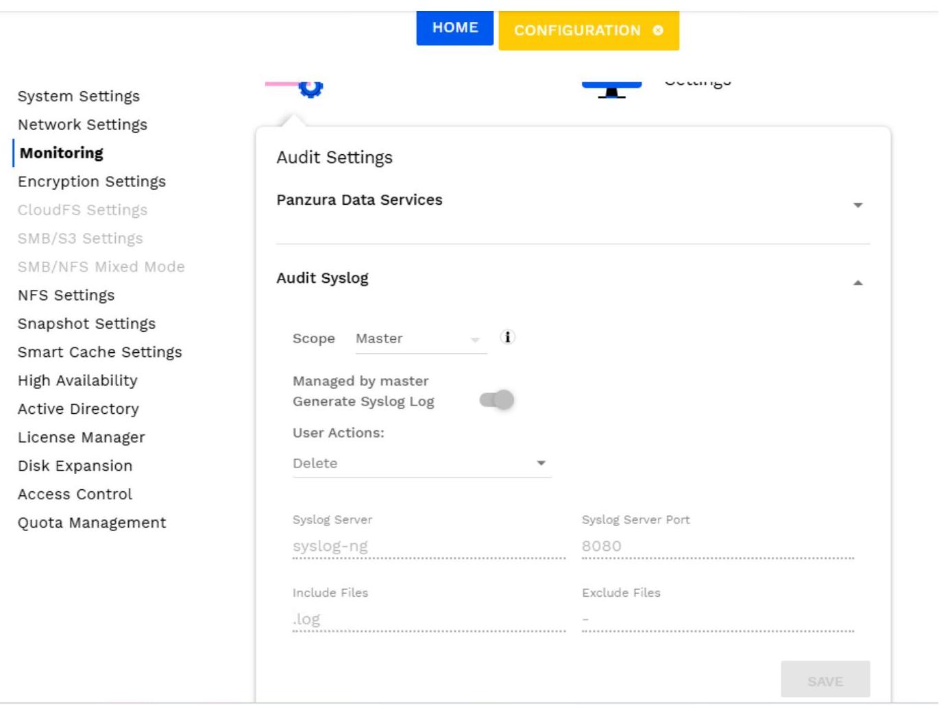 5. In Third Party Vendor Support (used for integrations) section:
a. Select the Scope.
5. In Third Party Vendor Support (used for integrations) section:
a. Select the Scope.
- If you are setting the scope on the Master node, then the Scope options are Ring and Local.
- If you are setting the scope on the Subordinate node, then the Scope options are Master and Local. To inherit Audit settings from the master node, toggle Inherited from Master on. b. To add a new Third Party vendor, click Add. c. In the Add Third Party Vendor Support window: d. Select Vendor Name. If you do not find the vendor name that you are looking for, ensure that the vendor is registered with CloudFS. For details, refer Register a Third Party Vendor with CloudFS. e. Select User Actions to enable or disable specific functions for users. f. You can Include Files and Exclude Files as required. g. If you are setting the ring scope on the Master node, then the Push to Subordinate(s) option is displayed. Select this option to push the settings to all the subordinate nodes in the ring (you don't have to go and explicitly set the same on each node). h. To generate audit logs, toggle Generate PDS Audit Log on. If the Push to Subordinate(s) option is on and Generate PDS Audit Log is on, then all the nodes will start generating audit events. i. To generate a third-party log, toggle Generate Third Party Log on. j. Click Save.
The table lists the registered vendors and their settings. Administrators can edit or delete a vendor as required.
System Settings Network Settings Monitoring Encryption Settings CloudFS Settings SMB/S3 Settings SMB/NFS Mixed Mode NFS Settings Snapshot Settings Smart Cache Settings High Availability Active Directory License Manager Disk Expansion Geofencing Policy Access Control Quota Management
SNMP Users Data Services Settings
12.3.8 UX Dashboard & PZIQ Settings
Audit alert categories
Alerts displayed in the Notification Center:
- SYS.AUDIT.TP1.1 - Raised when audit event delivery to a configured third-party vendor is failing. The alert includes the vendor name and the consecutive failure count.
- SYS.AUDIT.TP2.1 - Raised when a vendor is enabled for third-party audit but RabbitMQ is not configured. The alert includes the vendor name and the number of dropped audit events.
12.3.8 UX Dashboard & PZIQ Settings
UX Dashboard
The UX dashboard is an additional dashboard available outside of the standard administrator credentials. It includes improved user metrics from a client experience metrics script in the customer environments.
To enable the UX dashboard, navigate to the following page in the CloudFS web UI:
| From CloudFS web UI | Description |
|---|---|
| Configuration Monitoring UX Dashboard and PZIQ settings Enable UX dashboard. |
Click the toggle to enable or disable the UX Dashboard. When the UX Dashboard is enabled, a link next to the UX dashboard option appears on the web UI as "Launch UX Dashboard Stats". The UX dashboard can be viewed outside of the CloudFS web UI and does not require admin access. Note: After the UX dashboard is enabled, the initial set of matrices may not be available for few minutes. |
| Advance dashboard / Standard dashboard button | On clicking this button, the dashboard view id switched between standard and advance view |
| Severity . | Describes the total of warnings, critical and informational |
| Policy . | Describes the total of network x1, cloudfs x1, disk x1 etc |
| 1HR, 6HR, 12HR, 1D, 1W | Different time frames for the data |
| Replication CSV and Node Stats CSV | Links at the bottom right of the dashboard provide access to the raw data used to generate the dashboard. |
To access the UX dashboard:
- Link to access the UX dashboard - https://dist/dashboard.html
- You are logged in to UX dashboard with "Advanced dashboard" view by default.
By clicking on the "Advance dashboard", you can switch the view to Standard dashboard. Advance dashboard view includes -
| Title | Description |
|---|---|
| System Events | List of system events and alerts with the timestamp, policy, severity and description. |
| Metadata Replication | Note: To display data in this window, it needs at least two node in a ring, like one master node and one subordinate node. |
| User Experience* | Provides latency for various SMB operations from the SMB client side. Note: Need to configure the PowerShell on the node. Contact Panzura Support either by logging in to portal or by sending an email to [email protected] to install the PowerShell on the respective node. |
| Bandwidth Utilization | Network throughput for Object Store (WAN) access and SMB, NFS (LAN) access in kilobytes per second. |
| Dirty Cache | Amount of data in bytes that need to be uploaded to the object store. |
| Snapshot Deficit | The number of snapshots the node needs to synchronize to be fully up to date. |
| CPU Used | Overall CPU utilization for the node. |
| Managed Capacity | Amount of Cloud storage used compared to the total capacity licensed. |
| SMB User Count | Number of SMB clients connected to the node. |
| Replock Queues | Number of replock operations; transactions per minute and transactions per minute out-of-band. |
| Disk Reads | Rate of disk read activity for the listed devices. |
| Disk Writes | Rate of disk write activity for the listed devices. |
| Disk Busy Percentage | Refers to how active the listed devices are as a percentage. |
| Title | Description |
|---|---|
| Disk Read Throughput | Amount of data read from the listed devices in Megabytes per second. |
| Disk Write Throughput | Amount of data written to the listed devices in Megabytes per second. |
| Disk Latency | Time for disk operations to complete in microseconds. |
Note: When there is no data available in the node, the charts on the PZIQ dashboard appear empty.
Standard dashboard view includes -
| Title | Description |
|---|---|
| Metadata Replication | Note: To display data in this window, it needs at least two node in a ring, like one master node and one subordinate node. |
| User Experience* | Provides latency for various SMB operations from the SMB client side. Note: Need to configure the PowerShell on the node. Contact Panzura Support either by logging in to portal or by sending an email to install the PowerShell on the respective node. |
| Dirty Cache | Amount of data in bytes that need to be uploaded to the object store. |
| Snapshot Deficit | The number of snapshots the node needs to synchronize to be fully up to date. |
| CPU Used | Overall CPU utilization for the node. |
| Managed Capacity | Amount of Cloud storage used compared to the total capacity licensed. |
| SMB User Count | Number of SMB clients connected to the node. |
| Disk Latency | Time for disk operations to complete in microseconds. |
Note: When there is no data available in the node, the charts on the PZIQ dashboard appear empty.
PZIQ settings
PZIQ settings refers to a set of additional metrics for the CloudFS Statistical Collection System (SCS). These metrics aid the Panzura Support Team in monitoring the health of CloudFS nodes.
The PZIQ is a tool used to monitor the CloudFS node. The table below lists the additional objects in the Panzura node Management Information Base (MIB) available when PZIQ settings are enabled.
PZIQ settings is enabled by default but can be disabled if required. Contact Panzura Support either by logging in to portal or by sending an email to [email protected] for more information or to disable PZIQ settings.
The PZIQ metrics is available on the know.panzura knowledge portal for reference.
12.3.9 Grafana and Time-Series Stats Settings
Multi-dashboard drill-down architecture ( 3 JSON files), multiple ring support, Grafana Cloud support, executive overview, traffic light summary, metadata stats, configurable column visibility.
The Time-Series Stats Settings feature enables the export of CloudFS data to a time-series database called InfluxDB, enabling seamless integration of CloudFS with monitoring tools like Grafana for visualization through pre-configured dashboards.
Organizations can use their monitoring solutions (like Grafana) pointing to this CloudFS time-series database to visualize real-time system activity, storage performance trends, and overall operational health of their CloudFS deployment.
The multi-dashboard drill-down architecture includes:
- Grafana Cloud support: Dashboards are now compatible with Grafana Cloud in addition to self-hosted Grafana instances. Connect Grafana Cloud (or any self-hosted Grafana instance) to CloudFS for real-time and historical monitoring of all systems, storage, network, cloud, SMB, and replication metrics.
- Multiple ring support: Users can now monitor multiple rings simultaneously via data source selection.
- Cross-dashboard navigation: Click-through drill-down from overview to ring to node level.
- Multi-dashboard architecture: Replaced the single-file dashboard with three interconnected dashboards providing a drill-down approach from estate overview to individual node metrics. Dashboard structure:
- Executive Overview dashboard: New top-level summary optimized for wall-mounted displays. Deployed using CloudFS_Executive_Overview.json.
- Ring Level Details dashboard: Statistics and detailed metrics for a selected ring. Deployed using CloudFS_Ring_Details.json.
- Node Level Details dashboard: Statistics and detailed metrics for a selected node. Deployed using CloudFS_Node_Details.json.
- Aggregation: Aggregated charts enable data visualization and analysis across configurable aggregation levels (Hourly, Daily, Weekly, Monthly, and Yearly) for a selected date range. Chart titles automatically indicate the selected aggregation level, and the selected date range must align with the chosen aggregation granularity to display data correctly. List of aggregated charts:
- Node Level Stats - Network >> Network I/O
- Node Level Stats - Network >> Node Drive Files Uploads Downloads Deletes
- CloudFS Ring Level Stats - Storage >> Managed Capacity Trend (This chart is displayed for the master node and is not affected by Node or Operations slicers. As Hourly aggregation is not supported for this chart, selecting it will display no data.)
- Traffic light summary widget: At-a-glance node health counts (red/amber/green).
- Configurable column visibility: Configurable table column visibility allows administrators to customize table views by showing or hiding selected columns using a column selector. The Cols: CloudFS Nodes Status filter is available on the Ring Level Details and Node Level Details view, while the Cols: Ring Level Disk Stats filter is available on the Ring Level Details view, enabling users to display only the columns most relevant to their analysis.
Available Dashboards for Grafana
| CFS version | Grafana Dashboard template version |
|---|---|
| CloudFS 8.7.1.0 | CloudFS_Grafana_Dashboard-v4.0.2.zip Includes: CloudFS_Executive_Overview.json, CloudFS_Ring_Details.json, CloudFS_Node_Details.json |
| CloudFS 8.6.1.0 - CloudFS 8.7.0.0 | CloudFS_Grafana_Dashboard-v3.0.1 CloudFS_Grafana_Dashboard-v2.0.5 |
| CloudFS 8.6.0.0 | CloudFS_Grafana_Dashboard-v1.0.2 (Refer to the Configure 2 InfluxDB data sources for template CloudFS_Grafana_Dashboard-v1.0.2 section for configuring the data sources on the Grafana on-premises version for this template.) |
Prerequisites
Enable InfluxDB Stats:
- Log in to the CloudFS Master Node WebUI using admin credentials or an RBAC user with the required access to the Monitoring section.
- Navigate to Configuration Monitoring Grafana & Time-Series Stats Settings section.
- In the Time-Series Stats Settings section, toggle Enable InfluxDB Stats option to ON and click Save.
- Click Get Credentials to configure this InfluxDB data source in your monitoring tool, such as a Grafana dashboard. Copy the URL and user credentials.
If you are using the Grafana on-premises version:
- Ensure that Grafana is installed in the CloudFS environment.
- Ensure that Enable InfluxDB Stats is ON.
- Ensure that the URL and user credentials are copied from the Get Credentials section. These details are required to configure this InfluxDB data source in the Grafana dashboard.
If you are using the Grafana Cloud version:
- Set up a Grafana Private Data Source Connect (PDC) connector on the Grafana Cloud platform. a. Log in to .grafana.net with valid credentials and required permissions. b. Navigate to Connections Private data source connect and click Create New Network. c. Enter a valid name for Private data source connect. d. Go to the Configuration Details tab. e. In the Choose your installation method section, select the Binary option. f. In the Use a PDC signing token section, edit the Token Name field if required and select an Expiration date as per the token validity requirements. g. Click Create Token. Copy and store the token when it appears. h. In the Deploy the PDC agent on your private network section, copy and store the values of Cluster and hosted-grafana-id.
Warning:
- During this procedure, it is recommended to use the data source names provided by Panzura.
- Ensure that the value added via the UI matches the value mentioned in the JSON file.
- CloudFS_Grafana_Dashboard=v4.0.1 include three JSON template files. When re-importing these templates, choose Overwrite to update the existing dashboards instead of creating duplicate copies.
- Templates released before CloudFS_Grafana_Dashboard=v4.0.1 can coexist with earlier versions, so they do not need to be overwritten.
Create a Dashboard in Grafana
- CONFIGURE THE DATA SOURCES
Note: This section does not apply to CloudFS_Grafana_Dashboard-v1.0.2. If you are using this template version, see Configure InfluxDB data sources for template CloudFS_Grafana_Dashboard-v1.0.2 instead.
On Grafana on-premise version:
- In Grafana Dashboard, go to Connections Data Sources.
- Click + Add new data source and then select InfluxDB.
- Add a new data source with the name cfs_scs_stats:
- Select Query Language as Flux.
- In the Http section, add the Url that was copied from the Enable InfluxDB Stats procedure.
- Set the Timeout as 300 seconds.
- In the Auth section:
- Enable the Basic Auth option. In the Basic Auth Details section, add the User and Password details that were copied from the Enable InfluxDB Stats procedure.
- To continue using the CloudFS-generated SSL certificate, enable Skip TLS Verify.
- To configure access using authorized CA-signed certificates, enable With CA Cert. Copy and paste the CA-signed certificate details in the CA Cert field in TLS/SSL Auth Details. For details about CA certificates, refer to the Install a CA-signed Certificate section in How to generate Self Signed and CA-signed Web Certificate.
- In the InfluxDB Details section:
- In Organization, enter panzura.
- In Token, add the Password that was copied from the Enable InfluxDB Stats procedure.
- In Default Bucket, enter cfs_scs_stats.
- Click Save & test. If the test is not successful, verify that the details added match this procedure. If it still fails after verification, contact Panzura Support.
On Grafana Cloud version:
- Log in to <username>.grafana.net with valid credentials and all required permissions.
- Navigate to Connections Data sources.
- Click the Add new data source button and select InfluxDB under the Time series databases category.
- Rename the data source; it is recommended to use the naming format provided by Panzura.
- Enter the URL obtained from the Get Credentials button on the Master Node.
- Select Product as InfluxDB OSS 2.x and Query language as Flux.
- Enable the Auth and TLS/SSL Settings toggle.
- Select the Basic Authentication tab and enter the Username and Password obtained from the Get Credentials button on the Master Node, and enable the With Credentials toggle.
- Activate the Skip TLS Verify toggle.
- In the Database settings section, enter Organization as panzura, Default bucket as cfs_scs_stats, and Password obtained from the Get Credentials button on the Master Node as the Token.
- Select the Private data source connect created for the CloudFS ring.
- IMPORT THE DASHBOARD TEMPLATE IN GRAFANA
Download the template JSON files for the Grafana Dashboard. Right-click the link and save the json file on your machine. If you are using the same JSON file to create another dashboard, change the UID.
Import the JSON file:
- In Grafana, go to Dashboards and click New Import.
- In Import dashboard:
- Upload the template JSON file. If you are using the same JSON file to create another dashboard, change the UID.
- Change the Name of the dashboard as appropriate, e.g. CloudFS Dashboard.
- Select cfs_scs_stats as the default data source for this dashboard.
- Click Import. On successful import, a new dashboard is created and displayed.
Monitor Grafana Dashboard with CloudFS statistics
In Grafana, go to Dashboards and select the dashboard that you created, e.g. CloudFS Dashboard. In the sample Grafana Dashboard using the template CloudFS_Grafana_Dashboard-v4.0.2.zip:
- Open the CloudFS Executive Overview dashboard. This dashboard provides a high-level, display-optimized view of ring-wise health, capacity utilization, node counts, and overall operational status across the environment. Select all available rings to populate the full summary for all rings simultaneously.
- To view the CloudFS Ring Level Details dashboard, follow any of these steps:
- Click on the Ring ID on the dashboard.
- In Select Data Source/Rings, select the Ring and then click Ring Level Details.
- Click Ring Level Detail and then select the Ring.
This dashboard provides detailed visibility into a selected ring, including ring summary metrics, node health distribution, traffic-light status indicators, and interactive filtering for rapid issue identification. 3. To view the CloudFS Node Level Details dashboard, follow any of these steps:
- Click on the Node ID on the dashboard.
- In Select Data Source/Rings, select the Ring and then click Node Level Details.
- Click Node Level Detail, select the Ring, and then select the Node.
This dashboard provides detailed node-level operational metrics and health information, enabling administrators to monitor performance, resource utilization, and diagnose issues on individual nodes.
Note:
- It is recommended to begin your monitoring session on the Executive Overview page.
- Each ring requires a corresponding data source to be configured.
- The Ring ID displayed throughout the dashboards is derived from the name assigned to that data source.
A compact summary widget at the top of the CloudFS Nodes Status panel displays total node counts in three color-coded categories:
| Colour | Indicates | Condition |
|---|---|---|
| Red | Critical | At least one metric at critical threshold: CPU , Memory , Swap , Load , Snap Deficit , Metadata Allocated , Metadata Free , or node not reporting for minutes. |
| Amber | Warning | At least one metric at warning threshold: CPU , Memory , Swap , Load , Snap Deficit , Metadata Allocated , Metadata Free , or node not reporting for minutes. |
| Green | Healthy | All metrics within normal operating range. |
Note:
- Color thresholds are aligned with per-row color coding in the node table, ensuring consistency between summary counts and the detailed view.
- Node level status precedence: Critical (Red) Warning (Amber) Healthy (Green).
- Status filters are interactive. Click on Total Nodes, Good, Warning, or Critical to filter the CloudFS Node Status table according to the selected status.
Configure InfluxDB data sources for template CloudFS_Grafana_Dashboard-v1.0.2
- Configure the data sources:
- In Grafana Dashboard, go to Connections Data Sources.
- Click + Add new data source and then select InfluxDB.
- Add a new data source with the name cfs_scs_stats:
- Select Query Language as InfluxQL.
- In the Http section, add the Url that was copied from the Enable InfluxDB Stats procedure.
- Set the Timeout as seconds.
- In the Auth section: A. Enable the Basic Auth option. In the Basic Auth Details section, add the User and Password details that were copied from the Enable InfluxDB Stats procedure. B. To continue using the CloudFS-generated SSL certificate, enable Skip TLS Verify. C. To configure access using authorized CA-signed certificates, enable With CA Cert. Copy and paste the CA-signed certificate details in the CA Cert field in TLS/SSL Auth Details. For details about CA certificates, refer to How to generate Self Signed and CA-signed Web Certificate.
- In the InfluxDB Details section: A. In Database, enter cfs_scs_stats. B. Add the User and Password details that were copied from the Enable InfluxDB Stats procedure.
- Click Save & test. If the test is not successful, verify that the details added match this procedure. If it still fails after verification, contact Panzura Support.
- Add a new data source with the name cfs_scs_stats-flux: i. Select Query Language as Flux. ii. In the Http section, add the Url that was copied from the Enable InfluxDB Stats procedure. iii. Set the Timeout as seconds.
iv. In the Auth section:
- Enable the Basic Auth option. In the Basic Auth Details section, add the User and Password details that were copied from the Enable InfluxDB Stats procedure.
- To continue using the CloudFS-generated SSL certificate, enable Skip TLS Verify.
- To configure access using authorized CA-signed certificates, enable With CA Cert. Copy and paste the CA-signed certificate details in the CA Cert field in TLS/SSL Auth Details. For details about CA certificates, refer to How to generate Self Signed and CA-signed Web Certificate. v. In the InfluxDB Details section: A. In Organization, enter panzura. B. In Token, add the Password that was copied from the Enable InfluxDB Stats procedure. C. In Default Bucket, enter cfs_scs_stats. vi. Click Save & test. If the test is not successful, verify that the details added match this procedure. If it still fails after verification, contact Panzura Support.
- Return to step # 2. Import the Dashboard template to continue with the creation of a Dashboard in Grafana.
12.3.10 Simple Network Management Protocol
Simple Network Management Protocol (SNMP) is an Internet Standard protocol that allows customers to monitor networked devices through a single tool. Devices that support SNMP include routers, modems, switches, and servers. SNMP monitors values exported by the SNMP agent and allows push notifications, which are traps in SNMP language. The two components of SNMP include SNMP agents and SNMP managers. An SNMP agent is a software on a managed device. The software allows the SNMP manager to communicate with the device using SNMP. The SNMP manager is an external software that queries, receives events, and gets responses from devices. A managed device implements an SNMP interface for node-specific information.
A Management Information Base (MIB) is a collection of information organized hierarchically. These are accessed using a protocol such as SNMP. MIBs are created by Managed Device vendors (Panzura), and they are stored on the device. MIBs must be provided to the SNMP manager so it knows how to translate the MIB values from the managed device. MIBs use a hierarchical namespace that contains object identifiers (OID). An OID identifies a variable that can be read using SNMP.
There are two transaction types: polling and traps. When polling occurs, the SNMP manager sends an SNMP request to a managed device at the default polling interval, which is 120 seconds. The managed device then responds with an SNMP response status. The second type of transaction is a trap or push notification. SNMP managers are always ready to receive a trap from a managed device. In order to receive and translate a trap from a managed device, the managed device must be configured to send traps to the manager, and the SNMP manager must be provided with a trap MIB from the managed device.
The following are the three versions of SNMP security:
- Version 1: Plain text authentication.
- Version 2: Improved authentication. Community strings are still transmitted over the wire in clear, plain text.
- Version 3: Provides the following three levels of authentication:
- NoAuthNoPriv - Users who use this level don't have authentication or privacy when they send and receive messages.
- AuthNoPriv - This level requires users to authenticate but does not encrypt sent or received messages.
- AuthPriv - This level is the most secure. Authentication is required and sent and received messages are encrypted.
You can download the MIB zip archive using the following URL: https://docs.panzura.com/PANZURA_SNMP.tgz After downloading the MIB archive, decompress it and load files into your SNMP manager. This download is also available by selecting Maintenance System Operations Download MIB . To configure the SNMP settings on a Panzura node:
- Log in to your Panzura node.
- Select Configuration Monitoring SNMP Users SNMP Settings.
- In the Read Community String field, enter the community string for read-only communication between the node and SNMP manager. Note: If you specify a custom community string, the public community string is disabled.
- In the Recipient IP field, enter the SNMP manager IP (this is where we send traps).
- In the Recipient Community String, enter the SNMP manager associated with community strings.
- In the SNMP Trap Threshold Settings field, Enter the usage thresholds (percent) that will trigger SNMP trap messages.
To edit a trap:
- Log in to your Panzura node.
- Select Configuration Monitoring SNMP Users SNMP Settings.
- In the SNMP Trap Thresholds section, select Actions Edit SNMP Trap.
To add an SNMP user:
- Log in to your Panzura node.
- Select Configuration SNMP Users.
- Click the Add button.
The following table displays the SNMP traps that Panzura Supports:
| Name | Trigger Condition | ID |
|---|---|---|
| prCloudControllerHighCPUUsage | cpu_load > threshold_value | SNMPv2- SMI::enterprises.32853.1.2.1.2.1000 |
| prCloudControllerHighMemoryUsage | (used_memory * 100 / total_memory) > threshold_value | SNMPv2- SMI::enterprises.32853.1.2.1.2.1001 |
| prCloudControllerHighDiskUsage | (used_disk * 100 / total_disk) > threshold_value | SNMPv2- SMI::enterprises.32853.1.2.1.2.1002 |
| prCloudControllerHighCloudUsage | (used_cloud * 100 / total_cloud) > threshold_value | SNMPv2- SMI::enterprises.32853.1.2.1.2.1003 |
| prTrapMetaSpill | (meta_space_used * 100 / total_meta_ssd) > threshold_value | SNMPv2- SMI::enterprises.32853.1.2.1.2.1004 |
| prTrapMetaAllocFail | vfs.zfs.metaslab.stats.mg_spill>100 and it keeps increasing | SNMPv2- SMI::enterprises.32853.1.2.1.2.1005 |
| prTrapActiveDown | /opt/pixel8/bin/pr_ping , failed for 3 times, we think the host is down, then this trap is sent | SNMPv2- SMI::enterprises.32853.1.2.1.2.1006 |
| prAutoFailover | AutoFailover occurred | SNMPv2- SMI::enterprises.32853.1.2.1.2.1007 |
| prRegularFailover | RegularFailover occurred | SNMPv2- SMI::enterprises.32853.1.2.1.2.1008 |
| prAlertTrap | An alert is shown on GUI, an email will be sent to customer, and 1009 trap will be sent also | SNMPv2- SMI::enterprises.32853.1.2.1.2.1009 |
| prCloudWriteFailureTrap | Sent when cloud write failures exceed threshold | SNMPv2- SMI::enterprises.32853.1.2.1.2.1011 |
| prWarnTrap | A warning is shown in theGUI, and an email will be sent to customer. Trap1009 is sent as well. | SNMPv2-SMI::enterprises.32853.1.2.1.2.1012 |
| prInfoTrap | Info is shown in the GUI, and an email is sent to the customer. Trap 1009 trap is sent as well. | SNMPv2-SMI::enterprises.32853.1.2.1.2.1013 |
| prSwapUsage | If the usage is greater then in the /usr/sbin/ swapinfo output, this trap is sent. | SNMPv2-SMI::enterprises.32853.1.2.1.2.1014 |
12.3.11 Syslog Message Categories
When using syslog to monitor for events needing attention, Panzura recommends monitoring for LOG_EMERG, LOG_ALERT, and LOG_CRIT.
- LOG_EMERG and LOG_ALERT messages typically represent conditions requiring immediate attention.
- LOG_CRIT events represent events that can become EMERG or ALERT if not addressed.
The following table provides a list of Syslog message categories.
| Syslog Message Category | Description |
|---|---|
| LOG_NOTICE | Conditions that are not error conditions but should possibly be handled specially. |
| LOG_INFO | Informational messages. |
| LOG_WARNING | Warning messages. |
| LOG_ALERT | A condition that should be corrected immediately, such as a corrupted system database. |
| LOG_ERR | Indicates a general error for general notification. Can occur often even on a node that is operating normally. |
| LOG_CRIT | Critical conditions, such as hard device errors. |
| LOG_EMERG | A panic condition. This message is normally broadcast to all users. |
| LOG_DEBUG | Messages that contain information normally of use only when debugging. |
12.3.12 Panzura MIB Objects
The Panzura node MIB provides access to the following types of system information and statistics:
- node ID, CloudFS version, and hostname
- Visibility into caching:
- Hot, warm, and cold for automated caching
- Hot, warm, cold for pinned files
- Cache hits/misses for automated caching
- Cache hits/misses for pinned
- Cloud statistics
- Number of drive files uploaded to cloud
- Number of drive files downloaded
- Number of upload failures
- Number of download failures
- SMB users
- Total number of SMB users currently connected to the node
- Total number of files locked by SMB users currently connected
- CloudFS local configuration
- Mode of node: master/subordinate
- Hostname of master node
- Local system snapshot information
- Latest system snapshot generated reference #
- Latest system snapshot uploaded to cloud reference #
- Date and time when the latest master snapshot was successfully generated
- CloudFS remote configuration
- Remote node hostnames
- Latency from node to remote node
- Remote node up or down
- Down means there is no communication
- Remote snapshot information from all other nodes
- Latest snapshot reference # synchronized from the specified remote node
- The latest snapshot reference # uploaded by the specified remote node
12.3.13 MIB Download*
The following table lists the objects in the Panzura Node Management Information Base (MIB).
| Object Name | Object ID (OID) | Type | Description |
|---|---|---|---|
| System Identification | |||
| ccSysCCID | .1.3.6.1.4.1.32853.1.4.1.1.0 | Sensor | The node's CCID |
| ccSysVersion | .1.3.6.1.4.1.32853.1.4.1.2.0 | Sensor | PFOS version |
| System Usage | |||
| cpuLoad | .1.3.6.1.4.1.32853.1.3.1.1.1 | Sensor | CPU usage averaged over the previous 5 minutes. Measures the number of processes waiting for CPU resources. |
| peCloudnodeHighCPUUsage | .1.3.6.1.4.1.32853.1.2.1.2.1000 | Trap | CPU usage averaged over the previous 5 minutes. Measures the number of processes waiting for CPU resources. |
| memUsed | .1.3.6.1.4.1.32853.1.3.1.2.1 | Sensor | Memory usage at the time of the measurement in KB. |
| peCloudnodeHighMemoryUsage | .1.3.6.1.4.1.32853.1.2.1.2.1001 | Trap | Memory usage at the time of the measurement in KB. |
| localHDUsed | .1.3.6.1.4.1.32853.1.3.1.3.1 | Sensor | Disk usage at the time of the measurement in KB. |
| peCloudnodeHighD | .1.3.6.1.4.1.32853.1.2.1.2.1002 | Trap | Disk usage at the time of the measurement in KB. |
| cloudStiskUsageatsUsed | .1.3.6.1.4.1.32853.1.3.1.4.1 | Sensor | Cloud usage at the time of the measurement in KB. |
| peCloudnodeHighCloudUsage | .1.3.6.1.4.1.32853.1.2.1.2.1003 | Trap | Cloud usage at the time of the measurement in KB. |
| High Availability | |||
| peTrapActiveDown | .1.3.6.1.4.1.32853.1.2.1.2.1006 | Trap | HA-Local active node failure notification. |
| Cache | |||
| ccStatCaHotAutoCache | .1.3.6.1.4.1.32853.1.4.2.1.1.0 | Sensor | The total number of bytes in data cache storage with an Auto Cache Smart Cache rule that were accessed during the last week. |
| ccStatCaHotAutoPinned | .1.3.6.1.4.1.32853.1.4.2.1.2.0 | Sensor | The total number of bytes in data cache storage with a Pinned Smart Cache rule that have been accessed in the last week. |
| ccStatCaWarmAutoCache | .1.3.6.1.4.1.32853.1.4.2.1.3.0 | Sensor |
| Object Name | Object ID (OID) | Type | Description |
|---|---|---|---|
| The total number of bytes in data cache storage with an Auto Cache Smart Cache rule that were accessed more than a week ago but less than one month ago. | |||
| ccStatCaWarmAutoPinned | 1.3.6.1.4.1.32853.1.4.2.1.4.0 | Sensor | The total number of bytes in data cache storage with a Pinned Smart Cache rule that were accessed more than a week ago but less than one month ago. |
| ccStatCaColdAutoCache | 1.3.6.1.4.1.32853.1.4.2.1.5.0 | Sensor | The total number of bytes in data cache storage with an Auto Cache Smart Cache rule that were accessed more than one month ago. |
| ccStatCaColdAutoPinned | 1.3.6.1.4.1.32853.1.4.2.1.6.0 | Sensor | The total number of bytes in data cache storage with a Pinned Smart Cache rule that were accessed more than one month ago. |
| ccStatCaCacheHits | 1.3.6.1.4.1.32853.1.4.2.1.7.0 | Sensor | The total number of cache hit bytes in data cache storage with an Auto_Cache Data Locality rule. |
| ccStatCaPinnedHits | 1.3.6.1.4.1.32853.1.4.2.1.8.0 | Sensor | The total number of cache hit bytes in data cache storage with a Pinned Data Locality rule. |
| ccStatCaCacheMissed | 1.3.6.1.4.1.32853.1.4.2.1.9.0 | Sensor | The total number of cache missed bytes in data cache storage with an Auto_Cache Data Locality rule. |
| ccStatCaPinnedMissed | 1.3.6.1.4.1.32853.1.4.2.1.10.0 | Sensor | The total number of cache missed bytes in data cache storage with a Pinned Data Locality rule. |
| ccStatCaEvited | 1.3.6.1.4.1.32853.1.4.2.1.11.0 | Sensor | The total number of evicted bytes in data cache storage. |
| Drive File Operations | |||
| ccStatCIUploads | 1.3.6.1.4.1.32853.1.4.2.2.1.0 | Sensor | The total number of drive files uploaded to cloud storage. |
| ccStatCIUploadFails | 1.3.6.1.4.1.32853.1.4.2.2.2.0 | Sensor | The total number of upload failures to upload a drive file to cloud storage. |
| ccStatCIDownloads | 1.3.6.1.4.1.32853.1.4.2.2.3.0 | Sensor | The total number of drive files downloaded from cloud storage. |
| ccStatCIDownloadFails | 1.3.6.1.4.1.32853.1.4.2.2.4.0 | Sensor | The total number of download failures to download a drive file from cloud storage. |
| SMB Users |
| Object Name | Object ID (OID) | Type | Description |
|---|---|---|---|
| ccStatSmbUsers | 1.3.6.1.4.1.32853.1.4.2.3.1.0 | Sensor | The total number of SMB users currently connected to the node. |
| ccStatSmbLockedFiles | 1.3.6.1.4.1.32853.1.4.2.3.2.0 | Sensor | The total number of files locked by SMB users currently connected to the node. |
| Snapshots | |||
| ccInfoLoSnLastGenSnapNum | 1.3.6.1.4.1.32853.1.4.3.1.1.0 | Sensor | The reference number of the latest snapshot generated by the node. |
| ccInfoLoSnLastUploadSnapNum | 1.3.6.1.4.1.32853.1.4.3.1.2.0 | Sensor | The reference number of the latest snapshot uploaded to cloud storage. |
| ccInfoLoSnLastMasterSnap | 1.3.6.1.4.1.32853.1.4.3.1.3.0 | Sensor | The date when the latest master snapshot was generated successfully. |
| Status of snapshot synchronization from remote nodes | |||
| ccInfoReSnIdx | 1.3.6.1.4.1.32853.1.4.3.2.1.1.1 | Sensor | Index number. |
| ccInfoReSnHostname | 1.3.6.1.4.1.32853.1.4.3.2.1.1.2 | Sensor | The remote node's hostname. |
| ccInfoReSnLastSyncSnapNum | 1.3.6.1.4.1.32853.1.4.3.2.1.1.3 | Sensor | The reference number of the latest snapshot synchronized from the specified remote node. |
| ccInfoReSnLastUploadSnapNum | 1.3.6.1.4.1.32853.1.4.3.2.1.1.4 | Sensor | The reference number of the latest snapshot uploaded by the specified remote node. |
| CloudFS | |||
| ccInfoCfsCfgIdx | 1.3.6.1.4.1.32853.1.4.3.3.1.1.1 | Sensor | Index number. |
| ccInfoCfsCfgHostname | 1.3.6.1.4.1.32853.1.4.3.3.1.1.2 | Sensor | The hostname of the node. |
| ccInfoCfsCfgFilesystemName | 1.3.6.1.4.1.32853.1.4.3.3.1.1.3 | Sensor | The filesystem name that the node is hosting. |
| ccInfoCfsCfgState | 1.3.6.1.4.1.32853.1.4.3.3.1.1.4 | Sensor | The operational state of the node. |
| ccInfoCfsCfgStatus | 1.3.6.1.4.1.32853.1.4.3.3.1.1.5 | Sensor | The status of the node. |
| Network latency from a node to other nodes in the CloudFS | |||
| ccInfocfsLaldx | 1.3.6.1.4.1.32853.1.4.3.3.2.1.1 | Sensor | Index number. |
| ccInfocfsLaHostname | 1.3.6.1.4.1.32853.1.4.3.3.2.1.2 | Sensor | The hostname of the node included in the CloudFS. |
| ccInfocfsLaHelloLatency | 1.3.6.1.4.1.32853.1.4.3.3.2.1.3 | Sensor | The network latency in milliseconds from the remote node. |
| ccInfoCfsCfgLoMode | 1.3.6.1.4.1.32853.1.4.3.3.3.1.0 | Sensor | The configuration mode of the node, i.e. master or subordinate. |
| Object Name | Object ID (OID) | Type | Description |
|---|---|---|---|
| ccInfoCfsCfgLoCfgMaster | .1.3.6.1.4.1.32853.1.4.3.3.3.2.0 | Sensor | The name of the master configuration node. |
12.3.14 Monitoring Recommendations for CPU Load
The amount of CPU load placed on a node is measured in terms of the number of processes that are ready to run and, in the queue, awaiting CPU resources. These are the recommended thresholds by model. (CPU load is measured by OID .1.3.6.1.4.1.32853.1.3.1.1.1.)
| Node Model | Number of Processes in the Queue and Ready To Run | Recommendation |
|---|---|---|
| 28xx models | Above 320 | Monitor closely |
| Above 400 | Look into it | |
| Above 800 | Take action | |
| 40xx models | Above 640 | Monitor closely |
| Above 800 | Look into it | |
| Above 1600 | Take action | |
| 5100 model | Above 480 | Monitor closely |
| Above 600 | Look into it | |
| Above 1200 | Take action | |
| 5300 and 5500 models | Above 960 | Monitor closely |
| Above 1200 | Look into it | |
| Above 2400 | Take action | |
| 6xxx models | Above 1200 | Look into it |
12.3.15 VM nodes
For nodes operating in virtualized environments, such as VMware ESXi or Amazon Web Services (AWS), first determine the number of CPU cores assigned to the node. When 4 cores are assigned, use the values given for the 28xx models.
For a larger number of cores, scale the values upward. For example, a node operating within AWS can have 8 cores. To scale the values, first divide the number of cores by 4 to get 2 . Next, multiply this by the values for the 28xx models. The CPU load recommendations become , and .
12.4 Encryption Settings
To upload pre-created certificates, navigate to the Configuration Encryption section. You can upload the following types of certificates:
- Encryption certificate: The encryption certificate is used to encrypt data that is sent to the cloud and decrypt data that is received from the cloud. You can use the default certificate provided by Panzura (not recommended) or use a custom certificate. When a custom certificate is loaded, it is visible in the list of encryption certificates. You can activate the custom certificate by clicking Activate in the Action column.
- Web certificate: The web certificate is presented when an administrator accesses the node web interface. You can upload a custom certificate to replace the default X. 509 PEM web authentication certificate.
The next subsections provide additional information about how certificates are used.
12.4.1 System Management
Web certificates are used when the administrator manages the node via a Web browser. This is a normal HTTPS security mechanism for guaranteeing the authenticity of a remote system, in this case the node. The node ships with a default X. 509 PEM web certificate issued and signed by Panzura. You can install a new replacement certificate through the web UI.
12.4.2 Data Encryption
The encryption certificate is used to encrypt data sent to the cloud and decrypt data that is read from the cloud. Each node ships with a default data encryption certificate (P12 formatted) that is issued and signed by Panzura.
The security web UI provides administrators with the ability to manage encryption certificates with flexibility, but care must be taken when doing this because nodes are fundamentally designed to share cloud data across multiple nodes, geographies, locations, and groups of users.
After a customer-issued certificate is loaded, it is displayed in the certificate list. You can select and activate any certificate, as described in this section. The following restrictions apply:
- All cloud nodes operating in a common single CloudFS must use the same encryption certificate for global read-write collaboration to operate successfully. Unpredictable data access and client IO experiences can occur if this certificate topology is not implemented.
- Although multiple encryption certificates can be loaded, each Panzura node uses one active certificate for all data operations. Multiple certificates cannot be active.
- When a different certificate is activated, the system uses the new active certificate to encrypt all new data while using older certificates, no longer active, to decrypt data that was encrypted with those certificates.
- You can delete a certificate only if it has never been activated. If the certificate has ever been used it must remain on the node.
12.4.3 Node-to-node Communication
During normal operation a node will communicate securely with other active nodes within a CloudFS. For security reasons this communication takes place using an SSH key pair. To change this key pair from the default shipped with the node, follow these steps.
Notes:
- Perform this procedure during a maintenance window across all nodes, including HA standby.
- If you use this procedure to change the key, then you must perform step 3 on any new node you add to the CloudFS.
To perform this procedure, port 443 must be open between nodes.
12.4.4 Key Management Interoperability Protocol Support
Panzura CloudFS supports Key Management Interoperability Protocol (KMIP). You use a KMIP server to manage KMIP certificates, including those for Panzura nodes. Only master nodes can interact with a KMIP server.
Communication with the KMIP server requires a mutually authenticated SSL session. You must upload the certificate authority (CA) certificate (the one that signed the KMIP server's server certificate) and client certificate for a KMIP server. Only one certificate of each type can be uploaded.
To upload another certificate, you must delete the certificate of that type that was previously uploaded. After uploading the KMIP related certificates, you can register encryption certificates.
12.4.5 Standard KMIP Port
IANA.org has assigned port 5696 for use by KMIP servers and clients. Your KMIP server documentation will state if it uses a different port number. The EMC RSA Data Protection Manager uses port 443 for KMIP communication.
12.4.6 Installing an Existing Key File (CLI)
If you plan to use an existing key file and want to use the CLI to do so, use the following steps.
- Make a note of the IP address of the master node. In a multi-master configuration, select a specific master node to be the designated key master for the purposes of this change. For the purposes of this procedure all other master nodes are treated the same as Subordinate nodes.
Change the pairing key on the master node:
- Use SSH to log in to the master node as admin. The cloudfs prompt appears. cloudfs>
- Type enable and enter "enable" as the password, as prompted. The prompt changes to cloudfs#. cloudfs> enable password: enable cloudfs#
- Use the show pairing-key command to display the current pairing signature and then use the regenerate-pairing-key command to create the new key. The second show key-signature command shows that the regenerated key is different from the original key. The value of the key signature can range from 2-43 characters, depending on the version of software that the node is running. cloudfs# show pairing=key value:zBCD3fyYegWr+vf9eFge6vExk+pfIPHkCcdYZO9hp0 cloudfs# regenerate=pairing=key cloudfs# show key=signature value:fGHEIK6MyEmRiGkDr+vf9eFge6vExk+pIEMsstO9qr4 cloudfs#
Change the pairing key on all other nodes, including and HA standby nodes.
- Use SSH to log in to the master node as admin. The cloudfs> prompt appears. cloudfs>
- Type enable and enter "enable" as the password, as prompted. The prompt changes to cloudfs#. cloudfs> enable password: enable cloudfs#
- Enter the resync-pairing-key command to specify the pairing key. Include the IP address of the master node and the admin password. If your nodes are using valid signed web certificates, use the secure option. If your nodes are using the default unsigned web certificate, use the insecure option. cloudfs# resync=pairing=key master=ip=address password secure cloudfs# or cloudfs# resync=pairing=key master=ip=address password insecure cloudfs#
- Run the check-master-key-pair-sync command to verify that the key on the master and Subordinate nodes are the same.
If the prompt returns with no output, the command is successful and the keys are identical: cloudfs# check=master=key=pair=sync
cloudfs# If the following error occurs, the sync was unsuccessful and you must rerun the resync-masterpairing-key command and then the check-master-key-pair-sync command: ERROR:keysync not done.
Repeat for all remaining Subordinate nodes.
12.4.7 Encryption Settings
| Settings | Description |
|---|---|
| Encryption Settings | 1. Click Add to add a certificate. 2. Enter a name to identify the certificate, and click Choose File to find and select the certificate file. 3. Enter and confirm a passphrase. This is the export password that is assigned when creating the encryption certificate from OpenSSL. 4. Click Add to make the certificate available for selection. |
12.4.8 Authentication Keys
| Settings | Description |
|---|---|
| Authentication Key | Key used by the nodes to communicate among themselves. Enter the key on the key master. 1. On the key master, click Export to export the pairing.key file. 2. On each subordinate in the CloudFS, click Upload to upload the pairing.key file that you exported from the key master. |
12.4.9 Web Certificate Settings
| Settings | Description |
|---|---|
| Web Certificate | 1. To install a new web certificate, select No custom certificate and then click Choose File. 2. Select a new X. 509 PEM certificate, click Upload and then click Activate. 3. Following upload, the name of the new certificate is shown. To delete a custom certificate, select it and click Delete. |
12.4.10 KMIP Server Settings
Configure connection to a Key Management Interoperability Protocol (KMIP) server and to manage KMIP certificates. (See Key Management Interoperability Protocol Support.)
Specify the following for connection to a KMIP server, and click Save:
| Settings | Description |
|---|---|
| KMIP Server Host Name | Specify the IP address or hostname of the KMIP server. |
| KMIP Server Port | Specify the port for communication with the KMIP server. |
| KMIP Protocol Type | Select one of the following: - binary TTLV (standard KMIP). - HTTP TTLV (RSA DPM). If you select this option, a Security Class field is displayed. Copy the security class specified in the EMC RSA Data Protection Manager product and paste it into this field. Note: If |
| Settings | Description |
|---|---|
| you change to a new KMIP server, you need to register all certificates with the new server. |
12.4.11 KMIP Certificates
Use this section to upload CA and client certificates (X. 509 PEM format).
- Select the certificate type (CA or Client) and click Choose File to specify the file.
- Click Upload. Following upload, the certificate is listed in the KMIP Certificates area as "KMIP Server CA Certificate" or "KMIP Client Certificate".
- Click to create and register a certificate. Specify a name for the certificate and click Create and Register. This action creates a self-signed certificate that lasts for five years (RSA 2048-bit encryption). The full certificate name is the hostname of the cloud node with the creation date appended. The created certificate will be registered on the KMIP server.
12.4.12 Create and Register Encryption Certificates
Create and register encryption certificates. Click Create, enter the information, then click Register.
12.4.13 Retrieve Encryption Certificate from KMIP Server
Specify the certificate and private key name, and click Retrieve to retrieve the certificate from the KMIP server. The certificate is added to the Encryption Certificates list in this section. For example, if you previously registered the certificate mycert, enter mycert-cert and my-cert-key and click Retrieve.
Note: If you have a master-master configuration, any retrieve operation should be done to all masters.
12.4.14 Generating a Self-signed Web Certificate
- You can download openssl binaries from http://www.openssl.org/ and install them on Windows or Linux. For Linux, check the distribution for the install package. Open a command prompt (or terminal if you are using Linux) and issue the following command. #openssl req =s509 =nodes =days 365 =newkey rsa:2048 =keyout ccl.pem =out ccl.pem This will create a certificate named cc1.pem that will be used to upload from the web UI. When the certificate is uploaded and activated, the web UI will refresh with the self-signed certificate.
- Click Apply to activate the certificate and deactivate the previously active certificate.
If you already have a certificate signed by a third party to convert into X. 509 PEM, open a text editor and paste the keys from the certificates for the certificate chain in the following order, and save as a PEM file.
- Private.key
- Domain.crt: For domain certificate
- Intermediate.crt: For the Intermediate certificate
- Root.crt: For the Root certificate
12.4.15 Generating a Self-signed Encryption Certificate
- You can download openssl binaries from http://www.openssl.org/ and install them on Windows or Linux. For Linux, check the distribution for the install package. Use the following command to generate a private key if one does not exist. #openssl genrsa =des3 =out cloudfs.key 2048 Because keys are sensitive information, make sure you store them carefully and encrypt them using a strong passphrase and cipher. You can use the DES, Triple DES, IDEA, or 128, 192, or 256-bit AES symmetric ciphers by adding des, des3, idea, aes 128 , aes 192 , or aes 256 flag to the command line. The default is triple DES (des3).
- To create a self-signed certificate using the private key that you generated, use the following command: #openssl req =new =s509 =out cloudfs.crt =key cloudfs.key The process prompts you for details to create a Distinguished Name (DN). Some fields have a default value, which you can change as needed. If you enter a
period (.), the field is left blank. The default values are read from the openssl.cfg file. For Common Name, specify the fully qualified domain name (FQDN) of the controller, for example, cc.panzura.com. You can leave the email address, optional company name and challenge password fields blank.
- Country Name (2 letter code) [US]: US
- State or Province Name (full name) []: California
- Locality Name (eg, city) []: San Jose
- Organization Name (eg, company) []: Panzura Inc
- Organizational Unit Name (eg, section) []: Support
- Common Name (eg, YOUR name) []: cc.panzura.com
- Email Address []:
- Issue the next command to bundle the p12. The command reads the encoded certificate and key and exports to a single PKCS#12 file. By default, the key will be encrypted with triple DES and you will be prompted for an export password (which may be blank). #openssl pkcs12 =export -in cloudfs.crt =inkey cloudfs.key =out cloudfs.p12 =name "Friendly Name" Notes: You can concatenate the root certificate and any other certificates in the chain into a single file (for example, root.crt) and included in the PKCS#12 file as follows: #openssl pkcs12 =export -in cloudfs.crt =inkey cloudfs.key =certfile root.crt =out cloudfs.p12
- In the node web UI, click Browse under Encryption Certificates to upload the CC1.p12 file, and then select it. Click Apply to activate the certificate and deactivate the previously active certificate.
12.5 CloudFS Settings
To view or assign CloudFS settings, navigate to the following page in the node's web UI Configuration > Distributed CloudFS Use this page to view and configure settings for file storage into the cloud, provided that you have installed a cloud storage license. For information on adding a cloud storage license, see File Access Auditing Support for SMB and NFS Clients.
Deletion from or modification of a node could result in loss of data. For this reason, deletion and editing are not supported in the web UI. Be careful when adding a node. If you enter incorrect information (or need to delete a node), you must work with Panzura Support either by logging in to portal or by sending an email to correct the information or perform the delete operation.
12.5.1 Configure nodes in CloudFS
Specify the list of nodes that are subordinate to this node. This option is configurable only on a node that is a master. The table lists the hostname of the node, the domain name, and the HA mode (active or standby). Click Add Node to add a Subordinate node to the distributed node group.
- Enter the hostname of the Subordinate node. The hostname must be an FQDN.
- Enter the domain name. The domain name must be a valid DNS domain.
- If you are configuring HA-Global, indicate whether this node will be an active or standby system. Set the mode to Active, unless you are configuring an HA standby node. See Encryption Settings for instructions on configuring a standby node.
- Enter the File System name.
- Click Add.
SMB Version Support
SMB support is disabled by default. When you enable it, SMBv1, SMBv2, and SMBv3 support all are enabled by default. CloudFS supports the following SMB versions:
| SMB Version | Default | Description |
|---|---|---|
| SMBv1 | Deprecated | Support for SMBv1 is deprecated. Fresh deployment: SMBv1 is Disabled by default. |
| SMB Version | Default | Description |
|---|---|---|
| SMBv2 (2.2) | Enabled | Existing deployment: SMBv1 can be disabled |
| and is captured in Audit logs. | ||
| SMBv3 (3.1.1) | Enabled | SMBv2 support is always enabled and cannot be |
| disabled unless you globally disable SMB. | ||
| Enabled | SMBv3 support can be disabled or enabled | |
| individually. | ||
| Note: On nodes upgraded from 6.x (6.3.1.5), | ||
| SMBv3 support is disabled by default. |
SMB Version Used for a Client Session
The SMB version the node uses for a session with a client depends on the SMB version supported by the client. The highest (and most secure) version supported by the client is used by the node. For example, if a client supports SMBv2 but not SMBv3, the node uses SMBv2 for sessions with that client.
SMBv1 is an unsecure version of SMB. Environments that no longer require SMBv1 can disable it with this setting. Microsoft originally made SMBv1 available in the mid-1990s as an IP-capable network communications protocol for use between Windows clients and file servers.
In 2013 Microsoft announced its intent to remove SMBv1 from future products, since it was superseded by later SMB versions. The node continues to provide SMBv1 support for those legacy clients who request to use it.
Supported SMB Features
CloudFS supports the following SMB features:
- SAMBA 4.5 (SMB server for FreeBSD)
- SMB encryption 3.0.2, 3.1.1 (AES-128-GCM)
- Backward compatibility with SMB 1.0 (has no encryption)
- Leases (file not directory)
- Secure negotiate
- Large MTU ( 9000 bytes)
- Durable file handles
- Re-authentication
The maximum path length in Windows is 1024 characters. The maximum path length in Unix is 4 K characters. The default maximum read size is 1 MB . If you enable the GRW feature, the maximum path length for Windows and Unix is limited to 1024 characters. The current CloudFS version does not support the following SMB version 3.1.1 features:
- Persistent file handles across system resets
- Hyper-V
- Transparent failover
- Scale out
- Directory leases
12.5.2 SMB Shares
The SMB Shares in CloudFS allow users to access and share files stored in cloud storage using the SMB protocol. This section consists of adding details of Share Target Path, Manage Share Access, and S3 Interface.
| SMB/S3 Setting | Description |
|---|---|
| Share Name | Enter the name of the share into the web UI. |
| Example: projects |
| SMB/S3 Setting | Description |
|---|---|
| Share Target Path | Path to the share, in the form /cloudfs/<node=FQDN>/<folder=name> Example: /cloudfs/star=01/projects: where star-01 is the hostname of the node. Connect to the share node FQDN cloudfs, where node name>: is the hostname of your node and cloudfs is the CloudFS administrative share. Refer to the documentation for the client operating system if you need the specific steps to accomplish this step. As an example, on Windows 7 select Start > Run and type the path to the share in the entry field. The /cloudfs share represents the top level of the filesystem and is for administrative purposes only. In environments where both SMB/CIFS and NFS are used, Panzura recommends creating separate paths for SMB/CIFS and NFS. Example: node FQDN cloudfs smb: and ccname cloudfs nfs: Network shares for end users must be created below this point, as follows. While connected to the cloudfs share: 1. Open the folder that has the same name as the node. 2. Within the folder, create a new folder. This folder will serve as the mount point for the share being created. For this example, the folder is named projects. |
| Manage Share Access | |
| Select Node(s) | Select the node(s) you want to restrict share access. |
| Node(s) To Restrict Share Access | List of node(s) that are restricted. |
| S3 Interface Access | |
| S3 Interface | Enable to create a new S3 Interface for the specified Share Target Path |
| Port | Enter a Port number within the valid range of 9001 to 10000. If the chosen port is already in use, select another available port and try again. |
SMB Settings
SMB Shares
SMB Configuration
SMB Shares
Search
Manage SMB Shares. To add a new SMB Share, click Add. For HA Local with a shared DNS hostname or shared IP address, access SMB shares only through the shared hostname or IP. Using the original node's IP address or hostname is not allowed. $\square$ Share Name Share Path Access Restrict ed 53 Gateway Actions $\square$ s3testshare1 /cloudfs/new-r ON - 9001 $\square$ s3testshare111 /cloudfs/new-r snaptest-M2-S ON - 9002 $\square$ s3testshare8 /cloudfs/new-r ON - 9004 $\square$ s3testshare112 /cloudfs/new-r ON - 9003 $\square$ s3testshare115 /cloudfs/new-r ON - 9999 $\square$ s3testshare116 /cloudfs/snapt ON - 9200 e...
| Simba | /cloudfs | new-ring12, sn | ON - 9005 | ||
|---|---|---|---|---|---|
12.5.3 Manage Share Access
Enterprise organizations often deploy CloudFS across multiple sites, regions, or business units, each with unique access requirements. Traditionally, ensuring that shares are only visible from specific nodes required complex workarounds or separate configurations.
The Manage Share Access feature transforms this experience by offering:
- Seamless Operational Isolation: Ensures that shares are only visible where needed, greatly reducing the chance of unintended access and enhancing overall data security.
- Effortless Multi-Site Management: Allows customers to confidently manage a unified CloudFS ring while easily maintaining site- or region-specific share visibility.
- Improved Compliance and Security: Helps meet regional or contractual restrictions by controlling data exposure even when user credentials might otherwise permit access.
- Flexible Administration: Enable administrators to easily configure, update, and enforce node-based share access without altering the share definitions or Active Directory permissions.
Using the CloudFS web UI, administrators can restrict the share access when creating or updating SMB shares for a specific node. Once specified, these shares are not visible and cannot be mounted on the restricted node.
Note:
- Applying share access restrictions will restart the SMB server on the applicable nodes. It is recommended to perform this action during off-hours to avoid disrupting any active workloads on these node(s).
- If a nested share with access restrictions already exists for some of the ring nodes, then to ensure consistent access control, apply either similar access restrictions to this share, or configure a Geofencing Policy to protect the subset of file system that requires restricted access.
Create a new SMB Share with access restrictions
- Log in to the CloudFS Master Node WebUI using admin credential or RBAC user having required access to SME/S3 Settings.
- Navigate to Configuration SMB/S3 Settings SMB Shares.
- Click Add to manage share access for the selected share.
- Provide the share name and target path. Select the node(s) you want to restrict share access.
Note: SMB share access restriction is only applicable to the node(s) other than the node mentioned in the Share Target Path. 5. Click Add, and then Save the configuration. 6. After the Share is created, WebUI will display the list of restricted nodes under Access Restricted.
Add SMB Shares
Share path should begin with /cloudfs and include the complete Universal Naming Convention (UNC) path to the target directory you want to share.
| Share Name | Share Target Path |
|---|---|
| Design | /cloudfs/ccnode01-id62/design |
Manage Share Access
Select a different node instead of the one mentioned in the Share Target Path.
| Revert Noute(s) | Node(s) To Restrict Share Access |
|---|---|
| ccnode01-id62 | ccnode06-id62 |
| ccnode02-id62 | |
| ccnode06-id62 |
The newly created share will not be visible from restricted node. The restriction setting will be saved on each node in the configuration file located at /mnt/data/pixel8.cfg
Update SMB Manage Share Access
- Log in to the CloudFS master node WebUI.
- Navigate to Configuration SMB/S3 Settings SMB Shares.
- Click the Edit icon of the desired share and update the details as applicable.
- Select/deselect the node(s) to manage access, then click Done and Save the configuration.
Edit SMB Shares
Share path should begin with /cloudfs and include the complete Universal Naming Convention (UNC) path to the target directory you want to share.
Share Name s3testshare8
Share Target Path /cloudfs/new-ring10/s3share1/sh
Manage Share Access
Select a different node instead of the one mentioned in the Share Target Path.
Select Node(s)
Node(s) To Restrict Share Access
S3 Gateway Access
Valid Port range is from 9001 to 10000. S3 Gateway Port 9004
CANCEL
DONE
Delete SMB Manage Share Access
- Log in to the CloudFS master node WebUI.
- Navigate to Configuration > SMB/S3 Settings > SMB Shares.
- To delete a SMB Share, either click the Deleted icon or select the share and then click Delete.

12.5.4 S3 Interface Access
As more organizations adapt to cloud-native applications, there's an increasing need to collaborate and manage unstructured data across both traditional file-based (SMB/NFS) and modern cloud-native (S3) applications. As a result, organizations often must implement additional object storage systems, adding complexity and operational costs. CloudFS S3 Interface enables seamless collaboration across CloudFS multi-protocol environment, including SMB, NFS, and S3 offering a unified, modern approach to managing unstructured data.
The SMB share data can be accessed using the standard S3 protocol through the S3 API and command-line interfaces like AWS S3. Any buckets and objects created via the CloudFS S3 service are also available through SMB and NFS, appearing as POSIX-compliant files and folders. CloudFS supports global read-write collaboration across both SMB and S3 protocols. Additionally, CloudFS provides the ability to enable the S3 interface for existing SMB shares. This feature utilizes CloudFS features such as data deduplication, compression, and replication for data managed through the S3 interface.
A CloudFS S3 service can be enabled either on a new SMB share or an existing share by providing a port number that is in the range of 9001 to 10000 . In a collaboration mode, it can be accessed from any node to create a bucket and upload an object to the SMB share.
Note: Ensure that the associated port number is enable in your firewall configuration. The S3 Interface is accessible from both WAN and LAN networks and can upload and download data from any node within the CloudFS deployment. In case of mixed protocols-based access, the top-level directories within SMB share map to S3 buckets where Subdirectories map to S3 object paths. Files within these directories map to S3 objects.
CloudFS S3 supports single file uploads up to a maximum size of 5 GB. For larger files, S3 multi-part upload feature is supported and does not impose any size limitations.
Note: While using multipart upload, ensure that the connection remains live by updating the timeout The S3 Interface is SSL-only enabled and uses CloudFS generated SSL Certificate by default. Based on requirement, to configure CA-signed certificates, refer How to generate Self Signed and CA-signed Web Certificate.
The access key and secret key of CloudFS S3 users are mapped to their Identity and Access Management system (IAM) credentials-such as those from Active Directory-ensuring consistent authentication and access control across protocols. Set up appropriate ACL for users and groups as only users with required permissions for a Share should be used. Other users will be authenticated but will not be able to manage the share as required. To access a specific share via a specific node by providing the user's AD credentials, request for an access key and secret key. An Access key session validity is associated with the user's AD session validity. The same access key can be renewed if the session is expired.
Warning: The Geofencing Policy and Manage Share Access in SMB Shares features can restrict user access. If access to shared data is limited by either of these features, users will also be restricted from accessing the data via both S3 and SMB protocols.
Create a new S3 Interface
- Log in to the CloudFS master Node WebUI using admin credential or RBAC user having required access to SME/S3 Settings.
- Navigate to Configuration > SMB/S3 Settings > SMB Shares.
- Click Add for new share or edit for existing share.
- For a new share, provide the Share name and Share Target Path. Ensure that Share Path begins with /cloudfs and includes the complete Universal Naming Convention (UNC) path to the target directory you want to share.
- Enable S3 Interface toggle option.
- Specify a Port number within the valid range of 9001 to 10000 . If the chosen port is already in use, select another available port and try again. Note: Ensure that this port number is enabled in your firewall configuration.
- Click Add.
- Save the configuration to enable S3 and SMB protocols for the share.
To configure access to S3 Interface with authorized CA-signed certificates, refer How to generate Self Signed and CA-signed Web Certificate.
Access the S3 Interface
To access a specific share on a node, use the CloudFS REST API with the user's Active Directory (AD) credentials to obtain a temporary access key and secret key. The CloudFS S3 Interface supports two implicit user authentication mechanisms:
- Kerberos Authentication (Recommended & Default):
- The system uses the Kerberos Ticket-Granting Ticket (TGT) for authentication.
- The granted access key and secret key pair remain valid according to the "Maximum lifetime for user ticket renewal" policy defined in your Active Directory configuration.
- Default Lifetime: 7 days (configurable in AD up to a maximum of 999 days).
- Post-Expiry: Users must request a new key pair via the REST API once the existing pair expires.
- NTLMv2 Authentication:
- The access key and secret key remain valid until the user's AD password expires.
- Recommended use case: This method is suitable for IoT or application-side usage where Kerberos may be less practical.
To modify these settings in the Windows AD environment, follow the steps below.
- Open Group Policy Management.
- Right-click the relevant Domain Policy (for example, Default Domain Policy) and select Edit.
- Navigate to Computer Configuration > Policies > Windows Settings > Security Settings > Account Policies > Kerberos Policy. Double-click Maximum lifetime for user ticket and Maximum lifetime for user ticket renewal to modify the values. Set the desired values and click OK.
Refer to the article for more details which is applicable to all the Windows Server versions. Note: These policy changes apply to all users in the AD domain and not to any specific individual user. The following example illustrates authentication using NTLM through a cURL command: Sample request:
$ curl =X POST https://<ipaddress>:9001/admin/v1/auth \
-=H "Content=Type: application/json" \
-d '("username":"as3user?", "password":"abcd123#","share":"mys3s1","Kerberos":false)';
Sample response:
("accessKey":"u1qVPT4XhapyqRoq2RT7RdTo4DCNNaUVSTCBjceq","nt1m":
("success":true),"secretKey":"jeVUmrmgvhaS1z0r82G8PCao7Tzr3AHJ1bALZHLL" )
Delete User Request To delete an existing user and remove the Kerberos token and session, use the following command:
$ curl =X DELETE https://<ipaddress>:9001/admin/v1/auth?user=as3user7 \
-=H "Content=Type: application/json" \
-d '("username":"as3user?", "password":"abcd123#", "share":"mys3s1", "Kerberos":false)';
Update an existing S3 Interface
- Click the Edit icon of the desired share and enable/disable S3 Interface or change the port number.
- Update as required. Enable/disable S3 Interface or change the port number.
- Save the configuration.
Delete an existing S3 Interface
- Select one or multiple shares and then click Delete.
Note: If a share is deleted, all the secret and access keys generated for accessing the same will no longer be valid. 2. Save the configuration.
12.5.5 SMB Configuration
| SMB/S3 Setting | Description |
|---|---|
| SMBv1 | Disables/enables SMBv1 support. |
| SMBv3 | Disables/enables support for SMB 3.1.1. (See SMB Version Support.) |
| SMB Signing Auto | Select an option for SMB signing. SMB signing is a security signature mechanism that can improve the security of the SMB protocol for Windows systems. Refer Overview of Server Message Block signing. 1. Disabled: SSMB1 signing is not offered between the client and node. For SMB2/3 protocol, by design, signing cannot be disabled. 2. Enabled: Signing is mandated for SMB1 session. A non-signed SMB1 session request from the client will be rejected. For SMB2/3, this will be treated as auto. If the client does not support SMB2/3 signing, the client responds with a message to that effect and the node allows a non-signed SMB session for that client. If your company enforces SMB signing at the client, and you are having connectivity issues, consider setting SMB signing to "Disabled" for testing. |
| SMB v3 Encrypt | Enabling SMBv3 allows for both encrypted and unencrypted traffic. Starting in CloudFS 8.1, users have the option of allowing only encrypted traffic by selecting the applicable option from available options in "SMBv3 Encryption". 1. Client Negotitated: Use the encryption configuration as defined by the Client. 2. Encryption Preferred: Encryption Preferred. 3. Encryption Required: Encryption enforced. |
Access-Based Enumeration
SMBv3 Hide CloudFS Share
Global Real-Time Collaboration
Select whether to enable Access-Based Enumeration (ABE). ABE is an administrative capability available to environments using Microsoft clients with shared files and folders. When enabled, users see only the files and folders they have permission to access. If a user does not have read permission for a specific folder, Windows hides the folder from the user's view. For example, ABE allows you to limit users to see only their personal home directory when they access the home directories shared folder.
Disables/enables support for SMB 3.1.1. (See SMB Version Support.) Hide root shares. Note: To create a new share when this option is enabled (root shares are hidden), you can do either of the following:
- Temporarily disable this option (Hide CloudFS Share), to make the / cloudfs root share visible, add the new share, then re-enable this option.
- Mount \hostname\ADMIN$. This mounts the /cloudfs folder. Then create the new share. Make sure to follow the recommended folder hierarchy described above under Share Target Path.
Enables Global Real-Time Collaboration:
- Click Add Application.
- Enter a name to identify the application. The application name is for user reference only. The node identifies the application by file extension.
- Enter the file extension for the application file type (example: .xlsx). Use spaces to separate multiple extensions.
- Click Save to save and start the collaboration process.
You can also select one or more entries from the Global Real-Time Collaboration list and do the following:
- Edit Application. Edit an entry.
- Import Application. Import an application file that was exported from another node.
- Enable/Disable. Enable or disable global real-time collaboration.
- Delete to remove selected entries.
- Export/Import. Export shares the settings with others. Import uses settings exported from another node.
GEOPAK Cross-site Collaboration
Enables support for multiple users across different sites using GEOPAK. To enable cross-site collaboration for GEOPAK, select Geopak from the application list, click More and selected Enabled Selected. Click Save. |
GEOPAK Cross-site Collaboration
This option enables support for multiple users across different sites using GEOPAK. In cross-site configurations the application requires the ability to communicate and coordinate where each user is making edits. Byte-range locking makes this possible. The Read File Consistency feature described above can be used to enable byte range locking for GEOPAK.
Global Real-Time Collaboration Recommendations
Panzura recommends using the Global Real-Time Collaboration option selectively, because it adds additional operations for the node. With many cross-site collaborative users opening numerous files, the network traffic to handle read consistency and additional load on the node's CPU should be closely monitored.
When a file is open on a CloudFS node, other clients connected to the same filer won't see the updated file's write time until the file is closed. This is done to optimize performance. However, clients connected to other nodes in the ring will see the updated write time. If you want all clients to see the updated write time immediately, you can contact Panzura support to include the following SMBD configuration change: smbd getinfo ask sharemode No
12.6 NFS/SMB Mixed Mode
The purpose of this chapter is to instruct the user on how to configure mixed mode for CloudFS. Follow the steps outlined in this document in sequential order unless otherwise noted.
12.6.1 CloudFS NFS/SMB Mixed Mode Details
There are two new configuration variables needed for mixed mode configuration:
- Mapping Type
- Currently three choices:
- hash
- auto-rid
- AD/LDAP
- ID Mapping Range
- Integer range (1-2147483648), system-wide
12.6.2 Mapping Type
The mapping algorithm is a system-wide parameter and is used to select which mechanism to map Windows SIDs to and from UNIX UID/GID entries. The current mechanism is called "hash" and is the default selection. For mixed mode, use "autorid" for the mechanism.
To support existing installs that do not intend to use mixed mode, Panzura suggests using "hash" as the default selection. Changing this parameter after the system has been in use may cause file access permission issues. Panzura recommends modification at the time of initial install only.
12.6.3 Panzura CloudFS 8.2.1.0 Features a New Mapping Type: AD/LDAP
AD/LDAP is intended for customer sites that are using LDAP services via Microsoft Active Directory (AD). These services are provided by the RFC2307 extensions to AD.
This configuration is often used by organizations that have a significant heterogeneous installation of Microsoft Windows and UNIX/Linux systems and wish to maintain a centralized control over user authentication and identity management.
In this case, the AD administrator is responsible for assigning a valid UID and GID to each user and group that will be accessing files from the Panzura CloudFS system. It is not strictly necessary for the UNIX/Linux clients to be joined to the AD domain, however it can make client configuration with winbind or SSSD easier.
12.6.4 ID Mapping Range
The mapping range is a system-wide parameter used to assign a UID/GID number for each SID that is presented to the system. Each SID represents a single security principle, such as a user or built-in system services. Each SID is mapped to a single number using the mapping algorithm, so the range must be large enough to accommodate the number of users it is expected to serve.
Warning: Changing this value after the initial configuration may cause users to lose ownership of their files. This value is not editable for the hash mapping type. For mixed mode, you must reserve some of the range for NFS clients that have UID's that are local to the client machine. The NFS clients and CloudFS must share the same range and the same mapping algorithm in order for the IDs to be mapped properly across systems. So, you must reserve some amount of space for wellknown IDs and local security principles.
Since it is not possible to determine this automatically, the system administrator must have the means to block off a range of IDs to be reserved for the clients. Most UNIX systems begin to allocate local IDs at roughly #1000; however, this is system dependent. A range of (20000-24999999) may be a reasonable default, but this should be adjustable to accommodate individual customer environments.
12.6.5 Reserved Mapping Range
This range is used to map users or groups that are either local IDs or built-in accounts. This range must not overlap the mapping range. It may span a range smaller than the start of the mapping range or larger than the end of the mapping range.
12.6.6 Additional Information
To configure mixed mode properly, it is necessary that all NFS clients use Active Directory for ID services. It is not necessary to enable LDAP or RFC2307 directory services.
You must also configure NFS clients using winbind and use the same mapping type and range as configured in CloudFS. This ensures that the mapping representing a user login is constant between both NFS and SMB clients. Additionally, this ensures that file ownership and file permissions are correct and constant.
Kerberos authentication/encryption is not required. NFSv4 is not required but is necessary for NFS clients that wish to display or modify ACLs. Warning: Mixed mode use is intended for NAS type workflows and is not compatible with simultaneous GRW access.
12.6.7 Configuring Mixed Mode for CloudFS
- From the Configuration screen in the CloudFS web UI, select SMB/NFS Mixed Mode from the navigation menu on the left side of the screen.
- Select Auto-rid from the Mapping Type drop-down menu.
- You may enter desired values in the Start and End fields or leave the default values as displayed on the screen.
- Click Save to apply the changes.
- Select SMB/S3 Settings from the navigation menu on the left side of the screen.
- Add an SMB share by entering your desired information in the following sections:
- Share Name
- Share Target Path
- Click Add to apply the changes.
- Select NFS Settings from the navigation menu on the left side of the screen.
- Add an NFS share by entering your desired information in the following sections:
- Use Network (on/off toggle)
- Filesystems
- Exports
- Host Network
- Permission
- Root Access
- Description
- Click Add to apply the changes.
- Click Save.
Notes:
- For information on using NFS mixed mode with SSSD, go to https://panzura.cloud.answerhub.com/articles/2253/using-nfs-mixed-mode-with-sssd.html.
- For information on troubleshooting CloudFS mixed mode issues, click https://panzura.cloud.answerhub.com/articles/1935/cloudfs-mixed-mode-trouble-shooting-guide.html.
- Changing the ID mapping method after initial configuration can cause unexpected side effects such as loss of file access or permissions issues, as well as file ownership issues.
- Currently, it is not possible to convert an existing Panzura CloudFS installation from normal operation to mixed mode operations consult with customer support.
- For enhanced security, using Kerberos for NFS exports is recommended.
- The use of NFSv4 is also recommended, as it allows for the use of fine-grained file permission control using NFSv4 ACLs.
12.6.8 Configuration Wizard
Only pertains to Panzura CloudFS? The configuration wizard manager opens when you click Continue with Optional Wizards at the end of the setup wizard. See the wizard's online help for details.
12.7 NFS Settings
To configure Network File System (NFS) settings, navigate to the following section Configuration > NFS. The NFS settings determine which NFS clients or subnets can access the data stored on the node. Clients use NFS to mount storage on the node. In addition to the host access control settings, the file system on the client is used to determine which users have permission to access individual files and directories in CloudFS.
- The NFS settings are active only if NFS is licensed and one of the NFS options is selected under the system settings. See https://know.panzura.com/systemsettings.
- The locking protocols for NFSv3 and NFSv4 are different. NFSv3 uses a network lock manager, whereas NFSv4 includes built-in file locking. To avoid compatibility issues, Panzura recommends keeping NFSv3 and NFSv4 on different exports. If you must use NFSv3 and NFSv4 on the same export, be aware that file range locking only works within NFSv3 or NFSv4, not between the two versions.
- Using NFSv3 with the nolock option is recommended when there is no concurrent file access from multiple clients and you want to continue using NFSv3.
- To use NFS on Windows, use nolock and fileaccess 777 . These are required for file write permissions.
- Windows 7, Windows 8, Windows 2012, and Windows 2012 R2 are not compatible with NFSv4 and therefore are not able to connect using the protocol. NFSv3 is recommended.
- In some cases, the NFS access control settings apply only to the NFSv3 mountd protocol.
- When a sub-directory is exported, if other sub-directories on the same filesystem (including the filesystem mount point itself) were previously mounted, the client might still be able to access the mount point. But the new mount access to the previous exported directories will be denied.
- For NFSv4, if any of the sub-directories was exported, the parent filesystem is also exported. So if /cloudfs//dir1 is exported, the client will be able to mount / cloudfs/ with NFsv4 if it is enabled.
- On the CloudFS node, the sysctl parameter vfs.nfsd.inodes32b needs to be set to 1 in order for the NFS server to use 32-bit inode numbers in calls like list directory. If not set, then 32-bit applications running from the NFS mountpoint at the client would fail. Please set below configuration on the CloudFS node and restart NFS daemon. Please contact the Panzura support team to get this configuration done. $ sysctl vfs.nfsd.inodes32b=1
12.7.1 Sample NFS Configurations
Example 1: Provide Maximum Access
In the following example, maximum access to the file system is provided for the specified network.
Filesystem Configuration
- Filesystem: /cloudfs/f01-cs
- Use Network: enabled
- Host/Network: 10.0.0.0/#
- Exports: (no directory specified)
- Permission: Read-write
- Root Access: Yes
- Alldirs Mount: Yes
The path /cloudfs/f01-cs is exported to network 10.0.0.0/#.
Example 2: Provide Granular Access
In the following example, access to a particular directory is provided for a particular host.
Filesystem Configuration
- Filesystem: /cloudfs/f01-cs
- Use Network: disabled
- Host/Network: 10.1.2.3
- Exports: dir1
- Permission: Read-write
- Root Access: No
- Alldirs Mount: No
The path /cloudfs/f01-ca/dir1 is exported to host 10.1.2.3.
Sample Mount Commands
If NFS is used for application that is not sensitive to IO errors, and user wants a better experience when the NFS server is temporarily unavailable. Only use the intr option for Linux kernel version 2.6.25 or prior. sudo mount -t nfs -o rw,bg,vers=3,tcp,raise=1048576,weise=1048576 10.0.0.92:/cloudfs/f01-ca /dir1
If NFS is used for IO error sensitive workloads, such as database workloads, do not use intr. Notice that the following command also specifies:
- the use of NFSv4 (vers=4) instead of NFSv3 (vers=3).
- hard as it serves its own distinct purpose (avoiding silent IO errors when the server is briefly unreachable).
To support NFSv4, you must enable it in the NFSv4 Settings section, as shown in the following table. sudo mount -t nfs -o rw,bg,nointr,hard,vers=4,tcp,raise=1048576,weise=1048576 10.0.0.92:/cloudfs/f01-ca /dir1
Note: The intr/nointr option for the following has been deprecated:
- Linux kernel version 2.6.25 onwards
- Red Hat KB (RHEL 6+) onwards
Host/Network Format for Export
The Use Network option controls the format for exported IP addresses.
Use Network selected:
Configure a network using either of the following formats:
- ip-address netmask
- ip-address/netmask-length
Examples:
- 10.1.1.0
Use Network not selected: Specify one or more hostnames or IP addresses. Use a space between each hostname or IP address as a delimiter.
12.7.2 NFS Exports
| NFS Setting | Description |
|---|---|
| Add Export | Click Add Export to include hosts for which the node will provide data storage. Use Network: Select if you want to specify a network of hosts. Filesystem: Select a file system from the drop-down list. Exports: Enter a directory within the selected file system. Host/Network: Hosts or networks to export (see details). Permission: - Read-only: Allows read-only access to files. - Read-Write: Allows read-write access to files. - No-root-Squash: Allows root users on NFS clients to access all files available on the NFS server. |
| NFS Setting | Description |
|---|---|
| Alldirs Mount: | |
| Options for NFS shares | - Yes: The client is allowed to mount any directory under the selected directory. - No: The client can mount only at the specified directory level. Root Access: - Yes: Root access is provided to the specified directory. - No: Root access is not provided to the specified directory. Description: Enter a text description (optional). |
| From the list of NFS shares, you can: | |
| Edit Export: Modify settings for a selected share. Export: Save the NFS shares to a file, which can be used to modify the configuration. Import: Import a file that was previously exported and edited to create NFS shares in a batch operation. |
|
| File format for export/import: id /cloudfs/<ccname> "directory" "host/network" read/write alldirs root=aquash enable/disable |
|
| Example: 0 /cloudfs/cr=hq=cc5a "test3 test4" "1.2.2.2" read-write no- alldirs no-root=aquash enable |
|
| Revert: Remove selected entries in the table. Delete: Delete selected entries in the table. |
12.7.3 Netgroup Settings
| NFS Setting | Description |
|---|---|
| Add Netgroup | Click Add NFS Groups to add a set of hosts as a netgroup. The hosts in the netgroup must be local (not synchronized throughout CloudFS). |
| Parameters: - Name: Specify a name for the group. - Hosts/Group: Enter a set of hosts using hostnames or IP addresses, or a combination of both. Use a space to separate entries. Examples: 10.1.1.1 10.1.1.2 10.1.1.3 host1 host2.example.com 10.1.1.1 host1 host2.example.com - NFS Group Type: Select Hosts to create a netgroup consisting of hosts, or Groups to create a netgroup consisting of a set of other netgroups. A netgroup functions as a unit when checking permissions for operations such as remote mounts, remote logins, and remote shell sessions. For remote mounts, the netgroup identifies and classifies machines. For remote login and shell sessions, it identifies users. |
12.7.4 NFSv4 Settings
| NFS Setting | Description |
|---|---|
| Enable v4 mode | Select to enable NFSv4 (default is disabled). |
| NFS Setting | Description |
|---|---|
| Kerberos | Select ad to control access to the NFS server. |
| Security | Select a security option. |
12.8 Setting up Snapshots
This section explains how to configure snapshots. Using the default snapshot schedule is recommended, however if your environment requires a different schedule, review this section before making changes.
All snapshots consume a small amount of storage space. It is important to balance the need for snapshots with the total amount of storage consumed by snapshots to ensure proper operation for end users. In extreme cases when these two factors are not balanced, end users will experience reduced system performance.
Snapshots are among the most space efficient available and consume a minimal amount of space. The size of a snapshot is a function of two factors: the rate at which end users create or change files, and the total size of all file changes.
CloudFS nodes can be deployed in a wide range of use cases and configurations. For the cross-site collaboration use case, the snapshot schedule of a node can affect other nodes within the same CloudFS. This is due to the metadata associated with each snapshot being shared across all nodes.
If the total space of the snapshot metadata on a node is large, it can affect the amount of available disk cache on other nodes, the result being an increase in the eviction rate of cached user data on the other nodes. To guard against this, some storage space was set aside for this purpose when the size of the nodes was assessed.
For multi-node deployments, an additional option is available on subordinate node to manage snapshot retention for that node. The Node Specific Snapshot Policy allows customized snapshot retention periods for file owner as well as data owner node. When enabled, it allows data owner node to retain a smaller number of user snapshots than the file owner node. This approach reduces snapshot metadata growth on data owner (leaf) nodes, reduces cache pressure without impacting access to file versions, as all versions are preserved on the file owner. This is more beneficial in large deployment with active workload.
To be able to use the Windows Previous Version capability, it is suggested to schedule a snapshot with 1,000 - 2,000 snapshots. If you have business reasons for needing to maintain hourly snapshots over an extended period of time, it is recommended that you use the -snapshot directory to recover files instead. Contact Panzura Support to confirm that your node has sufficient PRC for end-user data and the large number of snapshots.
Use the smb-add-gcfg allow browse snapshots=yes maintenance command to allow browsing of the -snapshot directory for each share. For more information, see smb-add_ggfg in Diagnostic Tools.
The snapshot schedule provides the ability to define the number of snapshots to retain. For example, the schedule below specifies the most current 24 hourly snapshots be retained. When a new hourly snapshot is taken, the oldest hourly snapshot is removed.
When a new snapshot schedule is enabled, periodically check the disk cache utilization of all nodes within the same CloudFS to ensure there are no negative effects. Should any occur, modify the schedule or contact Panzura Support either by logging in to portal or by sending an email.
12.8.1 Snapshot Settings
The snapshot settings have the following default values. The settings are described in detail in the table below.
- Number of Yearly snapshots to keep: 1
- Number of Monthly snapshots to keep: 11
- Number of Weekly snapshots to keep: 3
- Number of Daily snapshots to keep: 6
- Number of Hourly snapshots to keep: 24
- Number of Quarter-Hourly Snapshots To Keep: 4
Panzura cloud nodes are capable of 10 K snapshots when deployed with the cross-site collaboration feature disabled. The node must be properly sized to ensure sufficient space is available for both snapshots and end-user activity.
After setting values, click Save.
12.8.2 Node Snapshot Settings
| Snapshot Setting | Description |
|---|---|
| Node Specific Snapshot Policy | Enables node-level snapshot retention policies to be applied to subordinate nodes, allowing customized retention settings. When enabled, the values for the number of yearly, monthly, weekly, nightly, and hourly snapshots along with Limit hourly Snapshots to the selected times can be modified. |
| Enabled Scheduled Snapshots | Enable this option to activate the scheduled snapshot feature. When enabled, system snapshots are created automatically according to the applied policy. To customize and apply a snapshot policy, scheduled snapshots must be enabled. Note: Even if the Node Specific Snapshot Policy is enabled, the Enabled Scheduled Snapshots option must also be activated in order to edit the policy. |
| Number of Yearly Snapshots To Keep | One snapshot is taken every year on January 1st. By default, 1 yearly snapshot is retained (representing the most recent yearly backup). |
| Number of Monthly Snapshots To Keep | One snapshot is taken once per month. The system retains the last 11 monthly snapshots, covering approximately the previous 11 months. |
| Number of Weekly Snapshots To Keep | One snapshot is taken once per week. The system retains the last 3 weekly snapshots, covering the previous three weeks. |
| Number of Nightly Snapshots To Keep | One snapshot is taken every night. The system retains the last 6 nightly snapshots, covering the previous six nights. |
| Number of Hourly Snapshots To Keep | Every hour one snapshot will be taken and will be retained upto next 23 hours. Enter the total number of hourly snapshots to keep (default 24) and use the hourly checkboxes to specify a schedule. The system saves snapshots according to the schedule up to the total specified number of snapshots. For example, if you specify 20 for the number of hourly snapshots to keep and select 4 times from the hourly snapshot schedule, then the system saves 5 snapshots taken at each time, for a total of . |
| Number of Quarter-Hourly Snapshots To Keep | Enter the number of quarter-hourly snapshots to retain (default: 4). Use the quarter-hourly checkboxes to specify when snapshots are taken. The system creates snapshots according to the selected schedule and retains only the specified number of the most recent quarter-hourly snapshots. For example, if you select 3 hours in the schedule, the system takes 12 snapshots per day ( 3 hours snapshots per hour). If you set the retention value to 20 , the system retains the 20 most recent quarter-hourly snapshots. |
12.8.3 How to Enable the Node Specific Snapshot Policy
- Log in to the CloudFS subordinate node Web UI using administrator credentials or an RBAC user with Snapshot Settings access.
- Navigate to Configuration Snapshot Settings Node Snapshot Settings, enable Node Specific Snapshot Policy, click Confirm on the pop-up warning, and click Save. Warning: It is recommended to use this feature on a data node. Once the number of snapshots is set to a lower value, restoring older Point-InTime file versions via this node will no longer be supported. However, they will still be accessible from the file-owner node that keeps a longer snapshot history.
- Update the parameters as needed, then click Save to apply the changes. When the Node Specific Snapshot Policy, toggle is enabled, it applies only to the current node and does not synchronize with the master node. When disabled, the snapshot settings automatically synchronizes with the master node configuration.
Snapshot Settings
Node Snapshot Settings
Snapshot Manager
Node Snapshot Settings
Configure Node Snapshot Settings. Enable Scheduled Snapshots
Number of Yearly Snapshots to Keep 1
Number of Weekly Snapshots to Keep 3
Number of Hourly Snapshots to Keep 24
Hourly Schedule i
AM $\begin{array}{llllllllllllllllllllllllllllllllllllllllllllllllllllllllllllllllllllllllllllllllllllllllllllllllllllllllllllllllllllllllllllllllllllllllllllllllllllllllllllllllllllllllllllllllllllllllllllllllllllllllllllllllllllllllllllllllllllllllllllllllllllllllllllllllllllllllllllllllllllllllllllllllllllllllllllllllllllllllllllllllllllllllllllllllllllllllllllllllllllllllllllllllllllllllllllllllllllllllllllllllllllllllllllllllllllllllllllllllllllllllllllllllllllllllllllllllllllllllllll
12.8.5 Snapshot Manager
| Snapshot Setting | Description |
|---|---|
| Create Snapshot | Enter the snapshot name and click Create Snapshot. |
| Edit | Select the snapshot from the list and click Edit to update the snapshot name. |
| Delete | Click Delete to remove the snapshot. |
12.9 Setting Up Smart Cache
https://know.panzura.com/setting-up-smart-cache
To configure Smart Cache settings, navigate to the Configuration Smart Cache section. The node supports Smart Cache, which is designed to provide LAN speed access to data stored in the cloud. Cache policies allow you to select specific files and data blocks to be continuously cached locally in the node. Cache policies act on local or remote file systems and provide automated caching, or pinning, of file data. You can create one cache policy for each file system, and each policy can have multiple rules within the policy.
Panzura recommends using the auto cache action with prepopulate enabled. This ensures that files are available in disk cache for end users. Prepopulating makes the data available without forcing a reduction in cache.
Pinning allows an administrator to forcefully localize (pin) data in the cache within a node to provide guaranteed LAN speed performance. Because pinning consumes cache space, it should be considered only if needed for performance, with the trade-off between performance and cache space kept in mind.
12.9.1 Cache Settings
| Smart Cache Setting | Description |
|---|---|
| Enable Smart Cache | Select to enable smart cache. |
| Percent of Storage for Cache | Enter the percentage of storage that is reserved for cache. The default is , which is the maximum allowed value. Work with Panzura Support before changing this value. Contact Panzura Support either by logging in to portal or by sending an email to [email protected]. |
| Enable Auto Pre-Populate | Enables the node to pre-populate its cache for faster performance. |
| Maximum Percent of Storage for Cache | Enter the percentage of storage that is reserved for cache. The default is , which is the maximum allowed value. Work with Panzura Support before changing this value. Contact Panzura Support either by logging in to portal or by sending an email to [email protected]. |
| Cache all on Cloud Read | Select whether to enable or disable caching for read operations. Default is enabled. When a client requests to read a block of data, the node fetches the drive file, selects the block, and returns it to the client. Typically the entire drive file is kept in memory cache for a few seconds or minutes before being flushed. When the cache all on cloud read option is enabled, the entire drive file will persist in the cache until it is forced out, possibly for days or weeks. This feature can reduce the number of cloud reads required for files that are being frequently accessed by clients. The only potential downside is that other data in the cache will be flushed more frequently. |
12.9.2 Cache Policies
Smart Cache Setting Policy Parameters
Description
| Smart Cache Setting | Description Click Add a Policy, specify the new policy in one of the following ways, and click Add. - Policy Name: Add a name to identify the policy. - File System: Select a filesystem on which to base the policy. (If you have multiple nodes in the cloud file system, see Policy Location (Which node is it on?).) (https://know.panzura.com/setting-up-smart-cache\#PoliLocation) Default Action: Select a default action from the following: + Auto Cache: This is the standard behavior of the node. The node will evict blocks of a file as needed to accommodate new data. + Pinned: Applies a 'last out' policy to data. It avoids evicting data unless the cache is full and new priority data is being ingested. Pinned data will be evicted only as a last resort after other data to maintain normal operations. If you choose pinned as the default action, the only way to unpin is to specify the auto cache in a rule. Note: Panzura recommends that you keep the default action as auto cache and then use rules to assign pinning. |
|---|---|
| Rescan | Click the Rescan icon for a filesystem in the table to apply the policy to it. A dialog box opens to show the following options. Select an option and click Rescan Now to start the scan. - Entire File System: Initiates a full scan of the specified filesystem and applies the rule. - Partial Rescan: Provides the ability to selectively apply the rule based upon specified criteria, which can be a specific path, and/or a date range. Note: The rescan process consumes resources on the node. If possible, rescan for the policy at off-peak times. |
| Rule Parameters | Click Add a rule. - Rule Expression: The rule syntax is based on glob programming, with the available actions or auto cache or pinning added to a glob expression. The rules are case sensitive. (See Sample Rules.) - Rule Action: See Rule Actions. - Prepopulate: Prepopulating makes the data available without forcing a reduction in cache. Panzura recommends selecting enable. - Deduplication: Indicates whether to apply deduplication to the data. This option controls deduplication for files that match the rule expression. If you specify No, deduplication is disabled for those files. Setting this option overrides the global deduplication setting and allows you to optimize deduplication at a fine-grained level. For example, If you enabled deduplication globally on the Cloud FS page (Distributed CloudFS Settings), you can override that setting for mp3 files by specifying a rule for mp3 files and setting dedup to No. |
12.9.3 Policy Configuration Example
In the following example, a Smart Cache policy (also called a data locality policy) is configured.
- First, click the Add Policy button.

- It will prompt the following window. Name the policy, click the Add button. For example, it is called Policy-1.

- The new page appears as shown in the image. To create a new rule, click the Add Rule button.

- A window will appear. For example, add the following rule: /homedir/sampledir/*. Click Add button. This rule locally caches all files in the /homdir/ sampledir/ folder.

Note:
This section is meant only as an example. Your configuration may contain more rules, depending on the content to be cached locally.
- After configuring rules and adding them to a policy, click Save to save the changes.

12.9.4 Setting Up Cache Policies
Follow this process to set up cache policies. Details are in the following table.
- Click Add Policy.
- Add a policy name, select the filesystem, and verify the default action. Panzura recommends that you keep the default action as auto-cache and then use rules to assign pinning. Click Add. The policy is added.
- Click the arrow to the left of the policy, if needed, to display additional settings.
- Click Add Filesystem if you want to add another filesystem to the policy. Select the filesystem and default action and click Add. A filesystem can be included in at most one policy, so your choices are limited to filesystems that have not yet been assigned to a policy. You can also edit or delete a filesystem entry from the table.
- Click Add Rule to add a rule to the policy. See details in the following table. Rules are considered in the listed order. Use the Up and Down arrows to change order.
12.9.5 Policy Location (Which Node Is It On?)
If you have multiple nodes in the cloud file system, the Filesystem drop-down list has multiple entries. In this case, you must decide where to apply the policy: to the local node's file system, or to a remote node's file system on this local node. For example, assume that you have nodes at site A and B. You are working from site A, but the data of interest is on site B. For the policy, select the node B file system from the drop-down. Then when data is written to the remote file system, it is also localized on node A.
12.10 High Availability Settings
Panzura CloudFS High Availability (HA) maintains continuity of SMB and NFS file services when a node in a CloudFS ring becomes unavailable. Local HA (LHA) pairs an active node with a designated standby node that share a common Virtual IP (VIP) address or DNS hostname. If the active node goes down, the standby node can take over that identity so client connections are restored with minimal disruption.
To configure High Availability settings, navigate to the following page in the Panzura CloudFS web UI: Configuration > High Availability.
12.10.1 Panzura node HA Solutions
The following HA solutions are supported:
- HA Local: An active node is protected by a dedicated standby. When the active node fails, the passive standby assumes its identity and takes over operations. HA Local is similar to the methods used by legacy enterprise storage product. In this configuration, an active node is protected by a dedicated, passive standby. When the active node fails, the standby takes over ownership of the file system and the node operations. The following HA Local options are supported:
- Local: The active and standby nodes have different hostnames and IP addresses.
- Local with shared address: The active node and passive standby have an additional shared hostname and IP address, which simplifies the takeover process. (Maximum length of the shared hostname is 15 characters.)
- HA Global: One or more nodes are protected by one or more shared standbys, which can be separated geographically from the nodes they protect.
12.10.2 Sample HA Deployment
Consider a Panzura deployment with three working sites-Los Angeles, London, and Paris-and two sites provisioned for high availability (HA)—Phoenix and Amsterdam. A Panzura node is physically deployed at each site. Users at the three working sites connect to their local node, have a complete view of the shared file system, and experience LAN-speed access to data in the global file system.
In this example, the HA configuration is as follows:
- HA-Global: The node in Amsterdam protects both subordinates in London and Paris, as well as the master node in LA.
- HA-Local: The node in Phoenix is dedicated to protecting the master node in Los Angeles.
The following HA-Local deployment options are supported:
- Local: The active and standby nodes have different hostnames and IP addresses.
- Local with shared address: The active node and passive standby have an additional shared hostname and IP address, which simplifies the takeover process. (Maximum length of the shared hostname is 15 characters.)
12.10.3 Best Practices
- When configuring the shared VIP or DNS hostname, ensure the auto-failover feature flag is disabled. Auto failover is not currently supported.
- Confirm that all nodes in the ring are up, running, and healthy before enabling a shared VIP on the master node and before removing a shared VIP on the master node.
- Before setting up Local HA on a shared VIP for an existing master node, confirm that all nodes in the ring are up, running, and healthy.
12.10.4 Status Information Exchanged by the Active and Standby Nodes
The Active and Standby nodes (peers) exchange information in order to make a coordinated decision on triggering a takeover. The following information is exchanged between the two peers, over an SSH connection that is automatically established between the two nodes when the HA pair is configured:
- Cloud status: Determined by a configured number of upload/download failures over a period of time.
- File system status: Status of the file system (based on number of metaslab errors encountered).
- Import status: Based on whether the node successfully imports the file system after a reboot (either forced or unscheduled).
- Critical process failed: Triggers failover if all remaining retries for a process fail.
- Snapshot sync status: Determines eligibility for a failover based on snapshot sync status. If the snapshot sync status is 50 or more snapshots behind, failover is not allowed.
- Scheduled reboot: If the active node is scheduled to reboot, HA takes this into account and does not perform a failover when the rebooting node goes offline during its reboot.
- State change: Used to figure out whether the takeover is impending.
12.10.5 Setting Up HA
HA can be configured either during initial setup using the setup wizard, or later using the management web UI.
HA operations that are:
- Supported: LHA failover abort
- Not Supported: GHA failover abort, Auto failover
Configuring Local HA for an Existing Active Node
Note: Before configuring Local HA for the master node with a shared VIP, confirm that every node in the ring is active, up, and healthy.
- From the configuration wizard, set Configuration Mode to HA Local and enter the Master Node Hostname so the node can register and retrieve cluster configuration, including licenses.
- Under Peer-to-Peer Authentication Key, upload the peer-to-peer authentication key for the pairing and confirm it uploads successfully.

- Under Role, select HA Local, then provide the Master Node Name details.
- Provide the Active Node Name to be used for the HA configuration.
- If a Shared DNS Hostname is provided during configuration, it is applied to the active node. The active node must then be rejoined to the Active Directory domain for the change to take effect.
Removing Local HA Without Disrupting Active SMB I/O
- Go to Configuration > High Availability.

- Select the HA pair to remove, then click Unpair.
- Review the warning dialog and click to confirm.

Note: The Preserve VIP option is enabled by default. Leave the Remove VIP checkbox unchecked so HA protection is removed while SMB clients continue accessing shares through the existing VIP hostname - no Active Directory changes or client reconnection are required.
Replacing Local HA Without Removing the VIP
To replace the standby node in an existing pairing while keeping the shared VIP intact, follow the Unpair procedure in 'Removing Local HA Without Disrupting Active SMB I/O' section with Remove VIP left unchecked. This detaches the current standby node while the shared VIP remains active on the master node. A new standby node can then be paired to the preserved VIP using the configuration steps in Configuring Local HA for an Existing Active Node section.
Migrating Local HA to Another Platform (Removing the Shared VIP)
Two migration paths are available, depending on whether the environment can tolerate removing the VIP immediately or requires a temporary preservation period. READY TO REMOVE THE VIP DURING UNPAIR
- Unpair the HA configuration and select the Remove VIP option. Follow the instructions provided by the wizard.
Unpair HA Configuration
Remove VIP node01-pn2o-vip/10.64.84.200 from active node node01-pn2o. Warning: This will unpair the HA configuration and remove the VIP from the active node.
- HA protection will be removed
- SMB clients using the VIP hostname will lose connectivity
- The node must be rejoined to Active Directory
- Clients must reconnect using the node's original hostname
- This may cause application disruption
Do you wish to proceed? 2. Set up the new LHA VM on the target platform (for example, a cloud platform), then perform node configuration.
VIP PRESERVATION NEEDED BEFORE DOWNTIME
Use this path when the VIP cannot be removed immediately and needs to remain active until a scheduled downtime window.
- Preserve the shared VIP and continue running the I/O workload on the shared VIP.

- Remove the preserved VIP. Contact Panzura Support to perform this operation.
- Set up the new LHA VM on the target platform (for example, a cloud platform) and configure HA as required.

ABORTING A STUCK FAILOVER
- Monitor the failover logs under Maintenance High Availability (HA) Takeover Status. If the failover operation appears stuck, click Abort.
- Confirm the abort when prompted. As part of the failover-abort procedure, the administrator must consent to rebooting the standby node; the node may temporarily disconnect from the UI and will reconnect automatically after reboot.


12.11 Default Auto Prepopulate/Prefetching Features
The following prefetching operations occur automatically.
Folder Prefetching Based on Ownership Change
The node prefetches a folder whenever ownership of the folder changes from one node to another.
- This prefetching remains in effect for a folder for 3 days after ownership of the folder changes.
- This new type of prefetching is performed automatically.
- Prefetching continues until there have been no ownership changes for 3 days.
- We recommend users to 'Enable Auto Prepop' by default for a good experience and more robustness.
Automatic File Caching
The node automatically caches both read and written data:
- Written data is automatically cached.
- Read data that is not already cached is cached.
Automatic Block Prefetch
When a user requests a file, the node immediately prefetches the remaining blocks of the file. By automatically prefetching the file's blocks, the node provides rapid access to users who likely will require access to more of the file's blocks before finishing with the file.
File Block Grouping
Another optimization feature that the node automatically employs is file block grouping. File group blocking groups blocks based on either or both of the following:
- Filename. The blocks are in the same file.
- Time when the blocks are saved. Blocks of any files that are saved at around the same time are grouped into the same block files.
Adjacent Block Prefetching
For further optimization, when a drive file is downloaded, the blocks saved immediately before and after the requested file also are downloaded.
- The last block to be saved before a block of the requested file was saved also is downloaded.
- Likewise, the first block to be saved after a block of the requested file is saved also is downloaded.
12.11.1 Sample Rules
The following table shows some examples of rule use cases and the rules used to implement them.
| Data Locality Rule Use Case | Rule |
|---|---|
| Match a directory path, which always begins with the file system. The file system for the policy is /cloudfs/cc1-ca. |
homedir/sampledir/* This rule matches anything in the sampledir directory under /cloudfs/cc1-ca/homedir. |
| Match anything in a specified directory from any directory path. | /sampledir/ This rule matches any path that includes a sampledir directory, such as ../homedir/sampledir/, ../temp/sampledir/, or ../Dept/Sales/ sampledir/* |
| Match one unknown character. ?at matches Cat, cat, Bat or bat. | ?at This rule matches any of the following: 1. Cat 2. cat 3. Bat 4. bat |
| Match any number of unknown characters. | Sys* This rule matches each of the following: 1. Sys 2. System |
| Match a character as part of a group of characters. | [CB]at This rule matches both of the following: 1. Cat 2. Bat But the rule does not match either of the following: 1. cat 2. bat |
12.11.2 Escape Characters
To use a special character reserved for policy rule matching as part of a string, use an escape character: Sys:* This rule matches Sys* but does not match Sys#. For example, if you enter *.xls and then select Pinned as the action, the rule pins all files with a .xls extension.
12.11.3 Rule Actions
Each rule includes an action that the file performs when the rule is matched:
- Auto Cache: This is the standard behavior of the node. The node will evict blocks of a file as needed to accommodate new data.
- Deny: When this action is selected, the creation of files with names matching the glob expression is not allowed for that file system.
- Do Not Cache: This action effectively applies a 'first out' policy to the data. Data is cached but will be evicted first before other data if space is required in the node, regardless of the type of data.
- Pinned: Applies a 'last out' policy to data. It avoids evicting data unless the cache is full and new priority data is being ingested. Pinned data will be evicted only as a last resort after other data to maintain normal operations.
- Not Replicated: Causes the data not to be copied to the cloud. This creates an unprotected scratch or temp space and should be used cautiously since the data is temporary.
12.12 Active Directory
12.12.1 SMB/CIFS File System Security
CloudFS file system security is compatible with and adheres to the Microsoft SMB/CIFS architecture. Files and directories can have user permissions or group permissions known as Active Directory security ACLs.
The security ACL information is made available via Microsoft Active Directory network queries between the client, the Active Directory Forest, and the node. This relationship is established and initiated during the client login to the node.
12.12.2 Joining a Microsoft Active Directory Domain
The node is designed to participate in Microsoft Active Directory Enterprise Forest topologies and therefore does not support an SMB workgroup-only authentication model (an SMB network with no Active Directory Domain node).
An internal DNS server should be accessible to the node during the Active Directory join process. The node will try to understand the Active Directory topology during the join process and locate many Active Directory servers within the domain. These servers will be used as potential candidates during the join process.
The process of joining a node to an Active Directory domain will populate key domain security ACLs within the default BUILTIN groups. This facilitates global read-write SMB/CIFS file sharing access throughout the Panzura unified namespace for each node in CloudFS (such as ..\cloudfs\cc1, ..\cloudfs\cc2, ..\cloudfs\cc3).
By default, the Active Directory groups 'Domain Admins' and 'Domain Users' are members of the Active Directory BUILTIN groups. If additional domain ACL security is needed, these can be modified after successfully joining the Active Directory domain.
For SMB, the node needs to join the AD domain that enforces the RBAC policies. Enabling a storage device to join the AD domain can be delegated to any user with this privilege. Panzura has found that in most cases, AD administrators tend to manage the devices that can join the AD domain. For this reason, AD administrator credentials are required during initial setup of a node.
12.12.3 WebUI Authentication Using Active Directory
If the node has joined an Active Directory domain, you can set up your AD domain node to allow authentication to the Panzura node using Active Directory credentials without additional setup in the Panzura node. To use this feature, add the following two groups to the AD domain node: priv_panzura_admins , priv_panzura_users.
Set the group scope to Global and group type to Security. Users assigned to either of these groups can then log in to the Panzura node using their AD credentials. Both of the following username formats are accepted: username@domainname domainname\username To join the Active Directory domain that you configured, navigate to the node Web UI Configuration > Active Directory > Active Directory Configuration. Enter the required AD information and click Configuration > Active Directory > Join Active Directory Domain. Enter your Domain Administrator credentials and click the Join button. The page displays the name of the domain node (if configured) and the current Active Directory domain status.
If you are joining an Active Directory Read Only Domain Controller, see Adding a Read Only Domain Controller. To remove the node from an Active Directory Domain, navigate to Configuration > Active Directory > Join Active Directory Domain, enter your Domain Administrator credentials, and click the Detach button.
12.12.4 Active Directory Configuration
| AD Setting | Description |
|---|---|
| AD Domain Name | Enter the Active Directory domain name and click Save. |
| Domain NETBIOS | Enter the username of the NetBIOS domain. |
| Domain Controller (optional) | Enter the name of the preferred domain controller on your network. Example: ad2.panzura.com To see a list of available nodes, click the entry field. As a best practice, leave this field as is ("Any"). This optional setting allows you to choose a preferred domain node. However, configuring this optional field pins the Active Directory server selection. This can result in a scenario where an alternate Active Directory server will not be used when the pinned Active Directory server goes offline. |
12.12.5 Join Active Directory Domain
| AD Setting | Description |
|---|---|
| Join | Click the button to join the domain. The status is displayed above the button. If the node is joined to the domain, you can click Detach to leave the domain. When joining or detaching from the domain, you are prompted to enter the Domain Administrator username and password. |
12.13 License Manager
To add, activate, or deactivate other licenses on the node, navigate to the following section: Configuration > License. The system identifier shown near the top of the page is unique to each node and is used to generate and request licenses. You can also specify settings for file access auditing, as described in File Access Auditing Support for SMB and NFS Clients and Antivirus and Malware Scanning. For AMI nodes running within a public cloud to be added to a CloudFS configuration, installation of an AMI Interoperability license on all other nodes is required. Contact Panzura Support to obtain the licenses.
12.13.1 Managing Licenses
Panzura licenses can be installed using either of the following methods:
- License token: This the simpler method and is the default for deployments in which Secure Private Network Mode is disabled. A single 34-character token provided by Panzura is required. You enter this token either while running the setup wizard or in the Web UI as described here.
- Individual license files: This method is the only method supported for Secure Private Network Mode. Individual license files keyed uniquely to the node are installed.
Panzura license files are not the same thing as either cloud storage provider (CSP) licenses, or peer-to-peer authentication key files. CSP licenses are issued by your CSP and authenticate access to your cloud storage. Peer-to-peer key files authenticate peer-to-peer communication among all nodes that have the same master Node (including the master Node itself).
12.13.2 Installed Licenses Module
Perform the following operations as applicable to the license type, token-based or individual license-based licenses:
Add License
Upload a valid license file.
- A pop-up is displayed as Upload License.
- Click Choose File to locate the license file.
- Click Add to make the license available for activation.
Edit License
Modify the license details.
- Select the license to be edited.
- Click Edit and update the details to be modified.
Reload License
You can reload the license file.
- Select the license from the list.
- Click Reload to help license change take the effect.
Activate License
You can change the license status which is in 'New' or 'Deactive' status.
- Select the license from the list which is in 'Deactive' status.
- Click Activate to enable the license and take the effect.
Deactivate License
You can change the license status that is currently in 'Active' status.
- From the list, select the license in 'Active' status.
- Click Deactivate to disable the license.
Note: Licenses with 'New' status cannot be deactivated. A license must be in 'Active' status to be deactivated.
Delete License
You can delete the license using 'Delete' option.
- From the list, select the license to be deleted.
- Click 'Delete'. Click 'Confirm' on the confirmation box.
The license is deleted from the list. Note: Managed Capacity licenses must be purchased in whole TB increments, starting with a minimum of 25 TB . Subsequent purchases can be 5 TB or more (for example, or 100 TB ) up to . For further assistance, contact Panzura Support either by logging in to portal or by sending an email to [email protected].
12.13.3 Activate License Token
Use this option to add additional license tokens to the existing ones, or to override specific components of an existing license with a separate token. You can create and upload the required token through this option. Provide the following details and click 'Activate'.
- License Token 2. CSP size 3. Unit 4. Cloud Type
12.13.4 S3 API Signature Version
When an API request is made with details such as the access key, secret key, payload, and headers, a security signature is generated. This signature is then used to validate the request, after which the request is processed and a response is returned."
Provide the following details and click Confirm. CSP Provider Name: Bucket Name: Path: Select the signature version: V2 or V4
CMP
Provider Name: Bucket Name: Path: Select the signature version: V2 or V4
12.13.5 S3 Storage Class (Configure S3 Storage Class)
Organizations had to manage storage class tiering outside of CloudFS, making the process complex, time-consuming, and potentially cost-ineffective. The Storage Class configuration feature helps administrators reduce costs and simplify storage management by assigning objects to the appropriate storage class.
Note: In CloudFS, the objects once created cannot be modified. When a file is updated or changed, CloudFS generates new objects to represent the modified portions while retaining the original objects as-is. The newly created objects are uploaded using the active storage class configured at the time of the update, while unchanged objects remain in their original storage class. By default, AWS uses Intelligent-Tiering, whereas Azure and GCP use their respective default storage classes. This behavior is consistent across all the supported cloud providers.
Important rules with respect to overriding the storage tiering in CloudFS:
- You can change or override the tier in any point of time.
- After changing the tier, the new data will be navigated to the new tier selected and the existing data will remain in the previous storage tier itself.
CloudFS supports following storage class:
- AWS S3 Storage Class
- Azure Storage Class
- Google Cloud Platform (GCP) Storage Class
Note: Storage Class can only be configured for cloud provider at node level (for CSP and CMP), not for snapshot or file level.
AWS S3 Storage Class
Amazon S3 storage offers different access tiers for storing the data in a most cost-effective manner based on the business usecase. The access tiers options available in Amazon storage class:
- Standard (S3 Standard)
- Intelligent Tiering (S3 Intelligent Tiering)
- Infrequent Access (S3 Standard-IA)
- Glacier Instant Retrieval (S3 Glacier Instant Retrieval)
AWS pricing details are available at: https://aws.amazon.com/s3/pricing/
Configure AWS S3 Storage Class
- Login to CloudFS master node master node web UI using administrator credentials or RBAC user having write access to License Manager.
- Click on Configuration tab.
- Navigate to License Manager > S3 Storage Class. Provide appropriate details and click Confirm.
CSP
- Provider Name - AWS
- Bucket Name
- Path
- Storage Class - Standard, Intelligent Tiering, Infrequent Access, Glacier Instant Retrieval (Select the storage class from the dropdown).
S3 Storage Class
S3 Storage Class
CSP Provider Name Amazon
Bucket Name
python-sanity-bucket
Path
automated-pipes-csp
Storage Class
Intelligent Tiering
CONFIRM
Edit AWS S3 Storage Class
- Select the respective AWS license.

| Installed License Modules | ||||||
|---|---|---|---|---|---|---|
| Installed License Modules | Search | |||||
| Manage installed licenses. | ||||||
| System Identifier: 42012652-341E-93C2-8687-25540AC735FC | ||||||
| License Module | Description | Duration | Expiration | Size | Status | Group Id |
| ^ | ||||||
| DS-Dedup | Data Services - De duplication Eval | 0 | 0 | Active | spfiler84R | |
| CSP-Amazon | Cloud Storage Am azon Eval | 0 | 0 | 25 TB | Active | spfiler84R |
| CMP-Amazon | Mirror Cloud Stora ge Amazon Eval | 0 | 0 | 25 TB | New | spfiler84R |
| Cloud Controller | License to Operat e Eval | 0 | 0 | 0 | Active | N/A |
| AS-Varonis | Application Servic es - Varonis | 0 | 0 | 0 | Active | spfiler84R |
| AS-Support Assist ance | Application Servic es - Support Assis tance Eval | 0 | 0 | 0 | Active | spfiler84R |
| AS-SecureErase | Application Servic es - To securely er ase data in the clo ud CloudFS Eval | 9 | 0 | Active | spfiler84R | |
| AS-NFS | Application Servic es - NFS | 0 | 0 | 0 | Active | spfiler84R |
| Click Add to upload the license files | ||||||
| ADD | EDIT | RELOAD | ACTIVATE | DSACTIVATE | DELETE |
- Click EDIT, select the required 'Storage Class'.
Edit License
Warning! This operation may reboot the system, stop all current read/write operations, delete all data stored in the storage and clear all reporting statistics.
PATH automated-pipes-csp
CLOUD HOST IP/NAME https://s3.us-west-2.amazonaws.
S3 ACCESS KEY AKIA5HRPSHPGKX4WUYWF
S3 SECRET KEY Required
BUCKET python-sanity-bucket
S3 API SignatureVersion V4
Storage Class Intelligent Tiering SSE-KMS
Azure Storage Class
Azure storage class option is provided to manage and save costs for customer expansion storage needs. It is helpful to organize data based on how frequently the storage tiers are accessed.
The Azure storage offers different access tiers for storing the blob data in a most cost-effective manner based on the usage. The table states the options available in Azure storage class: 1. Hot 2. Cool 3. Cold 4. Archive
These tiers are also known as online tiers and have latency in milliseconds with hot tier having least and cold tier having highest latency. Azure pricing details are available at: https://azure.microsoft.com/en-us/pricing/details/storage/blobs/
Configure Azure storage class
- Login to CloudFS master node master node web UI using administrator credentials or RBAC user having write access to License Manager.
- Click on the Configuration tab.
- Select License Manager > S3 Storage Class.
- You will see the following details on the S3 Storage Class. Provide appropriate details and click Confirm. CSP
- Provider Name - Azure (non-editable)
- Container Name
- Path
- Storage Class - Hot, Cool, Cold (Select the storage class from the dropdown).
CMP
- Provider Name - Azure
- Container Name
- Path * Storage Class Hot, Cool, Cold (Select the value from the dropdown).
- Navigate to storage account of Microsoft Azure (Home > Storage accounts). 6. Verify that the appropriate "Access tier" is applied to the objects which are getting uploaded to the cloud.
HOME CONFIGURATION 8
S3 API Signature Version
S3 Storage Class
S3 Storage Class
S3 Storage Class
CSP Provider Name Azure Container Name vscontainer Path auto1 Storage Class Cold CMP Provider Name Azure Container Name vscontainer Path auto2 Storage Class Cool
Note: A new storage class option called "Default" is introduced for Azure. User having Azure general purpose V1 Storage accounts must use the "Default" storage class option to deploy a CloudFS node. This "Default" storage class is applicable only for Azure Cloud CSP and CMP licenses.
After CloudFS nodes are configured, navigate to Configuration > License Manager > Storage Class, the "Default" storage class option must be selected for both CSP and CMP (if CMP is present) if the user has an Azure V1 Storage Account.
In the context of a general purpose V2 storage account, when the user selects the 'Default' storage class from the CloudFS UI, the blob is uploaded to the access tier that has been set by the user on their Azure storage account.
Google Cloud Platform (GCP) storage class
The GCP storage offers different access tiers for storing the data in a most cost-effective manner based on the business usecase. The access tiers options available in GCP storage class are:
- Standard storage: Is best for data that is frequently accessed ("hot" data), as well as data that is stored for only brief periods of time.
- Nearline storage: Offers a cost-effective, durable solution for infrequently accessed data, perfect for monthly analysis, backups, and archival needs.
- Coldline storage: Delivers ultra-low-cost, durable storage for quarterly-access data, balancing higher access fees with minimal at-rest costs.
- Archive storage: Offers ultra-low-cost, durable cloud storage with millisecond access, ideal for yearly-access data, backups, and disaster recovery.
For more details on the storage tiering and pricing, refer to Storage classes. CONFIGURE GCP STORAGE CLASS
- Login to CloudFS master node web UI using administrator credentials or RBAC user having write access to License Manager.
- Click on Configuration tab.
- Navigate to License Manager > S3 Storage Class. You will see the following details on the S3 Storage Class and click Confirm: CSP
- Provider Name - Google
- Container Name
- Path
- Storage Class - Default, Standard, Nearline, Coldline and Archive (Select the storage class from the dropdown).

Note: The "Default" storage class option is used to retain the storage class that is already configured at the bucket level in the Google Cloud Console. When this option is selected in CloudFS, no override is applied from the CloudFS UI. Instead, CloudFS continues to use the storage class defined directly in the Google Cloud bucket configuration. This ensures consistency between CloudFS and the native Google Cloud settings, allowing administrators to manage storage policies centrally from the GCP Console.
Refer to the section How to verify storage class set to the buckets for more details.
EDIT THE STORAGE CLASS
- Login to CloudFS master node web UI using administrator credentials or RBAC user having write access to License Manager.
- Click on Configuration tab.
- Navigate to License Manager > Installed License Modules and choose the GCP license.
- Click Edit, update the required 'Storage Class' and click 'Done'.
HOW TO VERIFY STORAGE CLASS SET TO THE BUCKETS
To verify whether the storage class of a bucket has been successfully set, you can perform the validation using both the gcloud command-line tool and the Google Cloud console.
Using the gcloud CLI, run the following command: gcloud storage buckets describe gs://<CSP/CMP bucket name> ==format="get (storageClass)". This command retrieves the current storage class of the specified bucket. The output should display the storage class value associated or set to the bucket. For example, if you have set the storage class to "NEARLINE", the command's output should return 'NEARLINE'.
You can also verify this using the Google Cloud console. Navigate to Storage > Browser, select the relevant CSP/CMP bucket, and open the Configuration tab. Under Default storage class, ensure that the displayed value matches the configured storage class. This confirms that the bucket's storage class update has taken effect.
Edit License
Warning! This operation may reboot the system, stop all current read/write operations, delete all data stored in the storage and clear all reporting statistics.
PATH

ACCESS KEY
SECRET KEY
Required
BUCKET NAME kshou
Default Standard Nearline CANDLE DONE Coldline Archive
The subordinate node should also reflect the same changes made on the master node. Navigate to storage account of Google Cloud (Home), locate for the object and verify that the appropriate "Access tier" is applied to the objects which are getting uploaded to the cloud.
12.13.6 Antivirus and Malware Scanning
This section describes how to configure McAfee VirusScan Enterprise and Symantec Protection Engine for antivirus and malware scanning.
McAfee VirusScan Enterprise 8.8 with VirusScan Enterprise for Storage
You can configure a node to use McAfee VirusScan Enterprise (VSE) 8.8 for antivirus and malware scanning. When installing the ICAP license on the node, you are prompted for configuration information.
Enter the IP address of the McAfee scanner into the Hostname setting of the ICAP license. No other setting changes are required. If you have multiple scanners and want to load balance between them, enter the IP addresses in the Hostname setting as a comma-separated list.
By default, the ICAP license scans files when a read or write occurs. If you do not want to scan on writes, enter no for Scan Fon Write. After the settings are configured, select the checkbox for the ICAP license and then activate the license at the top of the License Manager page. This will enable virus scanning immediately. If you need to change the settings later, enter new values and click Activate Selected at the top of the License Manager page. It is not necessary to deactivate the license to make configuration changes.
Symantec Protection Engine for Network Attached Storage 8.2.1 and above.
You can configure a node to use Symantec Protection Engine for antivirus and malware scanning. When installing the ICAP license on the node, you are prompted for configuration information.
Enter the IP address of the Symantec scanner into the Hostname setting of the ICAP license and verify that Deny on Error is set to no. If you have multiple scanners and want to load balance between them, enter the IP addresses in the Hostname setting as a comma-separated list.
By default, the ICAP license scans files when a read or write occurs. If you do not want to scan on writes, enter no for Scan on Write. After the settings are configured, select the checkbox for the ICAP license and then activate the license at the top of the License Manager page. This will enable virus scanning immediately. If you need to change the settings later, enter new values and click Activate Selected at the top of the License Manager page. It is not necessary to deactivate the license to make configuration changes.
12.13.7 Managing Configuration Changes
When you change configuration settings, the settings are in a pending state until you save them. The list of pending changes is shown on the right side of the Web UI window.
The category is shown along with the number and type of pending changes. You can review the changes before saving. To manage configuration changes:
- SAVE: Save all pending changes.
- CANCEL CHANGES: Discard all pending changes.
| Object Name | Object ID (OID) | Type | Description |
|---|---|---|---|
| System Identification | |||
| ccSysCCID | 1.3.6.1.4.1.32853.1.4.1.1.0 | Sensor | The node's CCID |
| ccSysVersion | 1.3.6.1.4.1.32853.1.4.1.2.0 | Sensor | PFOS version |
| System Usage | |||
| cpuLoad | 1.3.6.1.4.1.32853.1.3.1.1.1 | Sensor | CPU usage averaged over the previous 5 minutes. Measures the number of processes waiting for CPU resources. |
| peCloudnodeHighCPUUsage | 1.3.6.1.4.1.32853.1.2.1.2.1000 | Trap | CPU usage averaged over the previous 5 minutes. Measures the number of processes waiting for CPU resources. |
| memUsed | 1.3.6.1.4.1.32853.1.3.1.2.1 | Sensor | Memory usage at the time of the measurement in KB. |
| peCloudnodeHighMemoryUsage | 1.3.6.1.4.1.32853.1.2.1.2.1001 | Trap | Memory usage at the time of the measurement in KB. |
| localHDUsed | 1.3.6.1.4.1.32853.1.3.1.3.1 | Sensor | Disk usage at the time of the measurement in KB. |
| peCloudnodeHighD | 1.3.6.1.4.1.32853.1.2.1.2.1002 | Trap | Disk usage at the time of the measurement in KB. |
| cloudStiskUsageatsUsed | 1.3.6.1.4.1.32853.1.3.1.4.1 | Sensor | Cloud usage at the time of the measurement in KB. |
| peCloudnodeHighCloudUsage | 1.3.6.1.4.1.32853.1.2.1.2.1003 | Trap | Cloud usage at the time of the measurement in KB. |
| High Availability | |||
| peTrapActiveDown | 1.3.6.1.4.1.32853.1.2.1.2.1006 | Trap | HA-Local active node failure notification. |
| Cache |
| Object Name | Object ID (OID) | Type | Description |
|---|---|---|---|
| ccStatCaHotAutoCache | 1.3.6.1.4.1.32853.1.4.2.1.1.0 | Sensor | The total number of bytes in data cache storage with an Auto Cache Smart Cache rule that were accessed during the last week. |
| ccStatCaHotAutoPinned | 1.3.6.1.4.1.32853.1.4.2.1.2.0 | Sensor | The total number of bytes in data cache storage with a Pinned Smart Cache rule that have been accessed in the last week. |
| ccStatCaWarmAutoCache | 1.3.6.1.4.1.32853.1.4.2.1.3.0 | Sensor | The total number of bytes in data cache storage with an Auto Cache Smart Cache rule that were accessed more than a week ago but less than one month ago. |
| ccStatCaWarmAutoPinned | 1.3.6.1.4.1.32853.1.4.2.1.4.0 | Sensor | The total number of bytes in data cache storage with a Pinned Smart Cache rule that were accessed more than a week ago but less than one month ago. |
| ccStatCaColdAutoCache | 1.3.6.1.4.1.32853.1.4.2.1.5.0 | Sensor | The total number of bytes in data cache storage with an Auto Cache Smart Cache rule that were accessed more than one month ago. |
| ccStatCaColdAutoPinned | 1.3.6.1.4.1.32853.1.4.2.1.6.0 | Sensor | The total number of bytes in data cache storage with a Pinned Smart Cache rule that were accessed more than one month ago. |
| ccStatCaCacheHits | 1.3.6.1.4.1.32853.1.4.2.1.7.0 | Sensor | The total number of cache hit bytes in data cache storage with an Auto_Cache Data Locality rule. |
| ccStatCaPinnedHits | 1.3.6.1.4.1.32853.1.4.2.1.8.0 | Sensor | The total number of cache hit bytes in data cache storage with a Pinned Data Locality rule. |
| ccStatCaCacheMissed | 1.3.6.1.4.1.32853.1.4.2.1.9.0 | Sensor | The total number of cache missed bytes in data cache storage with an Auto_Cache Data Locality rule. |
| ccStatCaPinnedMissed | 1.3.6.1.4.1.32853.1.4.2.1.10.0 | Sensor | The total number of cache missed bytes in data cache storage with a Pinned Data Locality rule. |
| ccStatCaEvited | 1.3.6.1.4.1.32853.1.4.2.1.11.0 | Sensor | The total number of evicted bytes in data cache storage. |
| Drive File Operations | |||
| ccStatClUploads | 1.3.6.1.4.1.32853.1.4.2.2.1.0 | Sensor | The total number of drive files uploaded to cloud storage. |
| ccStatClUploadFails | 1.3.6.1.4.1.32853.1.4.2.2.2.0 | Sensor |
| Object Name | Object ID (OID) | Type | Description |
|---|---|---|---|
| The total number of upload failures to upload a drive file to cloud storage. | |||
| ccStatCIDownloads | .1.3.6.1.4.1.32853.1.4.2.2.3.0 | Sensor | The total number of drive files downloaded from cloud storage. |
| ccStatCIDownloadFails | .1.3.6.1.4.1.32853.1.4.2.2.4.0 | Sensor | The total number of download failures to download a drive file from cloud storage. |
| SMB Users | |||
| ccStatSmbUsers | .1.3.6.1.4.1.32853.1.4.2.3.1.0 | Sensor | The total number of SMB users currently connected to the node. |
| ccStatSmbLockedFiles | .1.3.6.1.4.1.32853.1.4.2.3.2.0 | Sensor | The total number of files locked by SMB users currently connected to the node. |
| Snapshots | |||
| ccInfoLoSnLastGenSnapNum | .1.3.6.1.4.1.32853.1.4.3.1.1.0 | Sensor | The reference number of the latest snapshot generated by the node. |
| ccInfoLoSnLastUploadSnapNum | .1.3.6.1.4.1.32853.1.4.3.1.2.0 | Sensor | The reference number of the latest snapshot uploaded to cloud storage. |
| ccInfoLoSnLastMasterSnap | .1.3.6.1.4.1.32853.1.4.3.1.3.0 | Sensor | The date when the latest master snapshot was generated successfully. |
| Status of snapshot synchronization from remote nodes | |||
| ccInfoReSnIdx | .1.3.6.1.4.1.32853.1.4.3.2.1.1.1 | Sensor | Index number. |
| ccInfoReSnHostname | .1.3.6.1.4.1.32853.1.4.3.2.1.1.2 | Sensor | The remote node's hostname. |
| ccInfoReSnLastSyncSnapNum | .1.3.6.1.4.1.32853.1.4.3.2.1.1.3 | Sensor | The reference number of the latest snapshot synchronized from the specified remote node. |
| ccInfoReSnLastUploadSnapNum | .1.3.6.1.4.1.32853.1.4.3.2.1.1.4 | Sensor | The reference number of the latest snapshot uploaded by the specified remote node. |
| CloudFS | |||
| ccInfoCfsCfgIdx | .1.3.6.1.4.1.32853.1.4.3.3.1.1.1 | Sensor | Index number. |
| ccInfoCfsCfgHostname | .1.3.6.1.4.1.32853.1.4.3.3.1.1.2 | Sensor | The hostname of the node. |
| ccInfoCfsCfgFilesystemName | .1.3.6.1.4.1.32853.1.4.3.3.1.1.3 | Sensor | The filesystem name that the node is hosting. |
| ccInfoCfsCfgState | .1.3.6.1.4.1.32853.1.4.3.3.1.1.4 | Sensor | The operational state of the node. |
| ccInfoCfsCfgStatus | .1.3.6.1.4.1.32853.1.4.3.3.1.1.5 | Sensor | The status of the node. |
| Object Name | Object ID (OID) | Type | Description |
|---|---|---|---|
| Network latency from a node to other nodes in the CloudFS |
|||
| cclnfocfsLaldx | .1.3.6.1.4.1.32853.1.4.3.3.2.1.1 | Sensor | Index number. |
| cclnfocfsLaHostname | .1.3.6.1.4.1.32853.1.4.3.3.2.1.2 | Sensor | The hostname of the node included in the CloudFS. |
| cclnfocfsLaHelloLatency | .1.3.6.1.4.1.32853.1.4.3.3.2.1.3 | Sensor | The network latency in milliseconds from the remote node. |
| cclnfoCfsCfgLoMode | .1.3.6.1.4.1.32853.1.4.3.3.3.1.0 | Sensor | The configuration mode of the node, i.e. master or subordinate. |
| cclnfoCfsCfgLoCfgMaster | .1.3.6.1.4.1.32853.1.4.3.3.3.2.0 | Sensor | The name of the master configuration node. |
12.13.8 Advance Settings
Regional Store Setup
Without regional store support, CloudFS utilizes same object store bucket for master and subordinate nodes regardless of their geographical regions. In such deployments, nodes may experience network latency and high cloud cost. The regional store support enables individual or group of subordinate nodes to do data upload and download from/to with its overridden dedicated cloud object store bucket.
The CloudFS nodes in regional bucket enabled- setup automatically detects replication failure across the buckets and seamlessly continue the node operation by syncing the data and metadata from the remote object store bucket wherever it is.
This per-node bucket mapping is configured through license settings, allowing nodes to interact with regionally optimized storage for improved performance and reduced latency.
The following diagrams illustrates how active nodes automatically download snapshots from other configured object store buckets when the dedicated bucket becomes inaccessible or replication between buckets is interrupted.
PANZURA

When a user connected to Subordinate-4 attempts to access "qtr_report.xlsx", the system first checks the local bucket (Bucket 3). If the file is not found locally, due to broken replication, it automatically retrieves the file from the data owner's bucket (Bucket 1).
The retrieved file is made available in read-only mode to maintain data consistency and prevent conflicts.
To configure the regional store:
- Log in to the CloudFS subordinate node web UI using administrator credentials or RBAC user with write access to License Manager.
- Navigate to Configuration -> License Manager -> Advance Settings.
- A toggle button is introduced called as "Regional Store Setup". Enable it. Use the same toggle button to disable the regional store bucket.
| HOME | MAINTENANCE | CONFIGURATION | |
|---|---|---|---|
| System Settings | |||
| Network Settings | |||
| Monitoring | |||
| Encryption Settings | |||
| CloudFS Settings | |||
| SMB Settings | |||
| SMB/NFS Mixed Mode | |||
| NFS Settings | |||
| Snapshot Settings | |||
| Smart Cache Settings | |||
| High Availability | |||
| Active Directory | |||
| License Manager | |||
| Disk Expansion | |||
| Access Control |
| HOME | MAINTENANCE | CONFIGURATION | |
|---|---|---|---|
| License Manager | |||
| Installed License Modules | |||
| S3 API Signature Version | |||
| Advanced Settings | |||
| Advanced Settings | |||
| Configure Specific License Properties | |||
| Regional Store Setup | |||
| Regional Store |
Note:
a. When you enable the toggle button, the CSP and the CMP licenses which are replicated from the master node can be overridden for that subordinate node. On a subordinate node, either the same master node CSP/CMP license can be edited to chose different regional store properties OR a completely new regional store license can be installed having type different than master node (For example, master has AWS S3 type bucket store and subordinate node needs Azure bucket store). b. Before enabling the regional store toggle option, the buckets that are configured with the master and subordinates must be in-sync with each other.
Edit regional store:
- Log in to the CloudFS subordinate node web UI using administrator credentials or RBAC user with write access to License Manager.
- Navigate to Configuration -> License Manager -> Installed License Modules.
- Select CSP (or CMP) license you want to change the bucket and click Edit.
- If the buckets are in the same region, change the Bucket Name. If the buckets are in the different regions, change the Cloud Host Name and Bucket Name. Click Done.
Note:
- If a subordinate node is switching to a new bucket, the data on the existing bucket must be manually copied to the new bucket before editing the regional store configuration.
- In case of updating the cloud access credentials or expiry of the credentials (access key id and secret key), contact Panzura Support to restart the supporting services.
- Regional Store allows deployment of multiple regional store buckets without enabling replication between them. However, when replication is not configured, ensure that the CMP is set up before enabling the regional bucket. CMP is supported only when replication is enabled across the buckets.
Configure new license with regional store is enabled
Using the regional store feature, you can configure different buckets in the cloud region. Add the new license of the cloud service provider and inactivate the existing cloud service provider. At a time only single bucket should be active for the subordinate node to upload the data.
- Navigate to License Manager -> Installed License Modules -> Add.
- The status on the license is New.
- Upload the license of the cloud service provider you want to configure. Click Add.
- Deactivate the existing cloud service provider license.
- Edit the new license with the appropriate values in the fields and click Done.
- Navigate to the S3 Storage Class option. Verify all the details are displayed with new license.
Deactivate the new license
- Navigate to License Manager -> Installed License Modules. Inactivate the license you want to discontinue.
- Navigate to License Manager -> Advanced Settings and disable the toggle button "Regional Store".
- Reboot the node. This ensures that all the subordinate nodes are matched with the previous configuration.
Note: After the Regional Store Setup is enabled on the subordinate node, any changes in CSP/CMP license on the master node won't be applied to that subordinate node.
LHA/GHA nodes configuration
When the Regional Store toggle is enabled on a subordinate node with a standby node: In the event of an active node failure, the standby node is expected to inherit all configurations of the active node and assume the active role. This automatic configuration transfer does not include Regional Store settings. To configure Regional Store support on the LHA/GHA node, you need to manually set it up, which also involves adding new buckets through the "Installed Licenses Modules" section.
12.14 Disk Expansion
Use this section to discover new disks that were added to your node (physical or virtual). If you have a physical node, go to the License Manager section and activate the disk license or licenses before you proceed.
In the Disk Expansion section, the table lists all of the discovered and provisioned disks.
A status line above the table indicates whether the status of all the disks is .

To discover and provision disks:
- Discover New. If you have installed an SSD expansion pack for your physical node, or new disks have been added to your VM node deployment, click this button to initiate a discovery. When discovery is complete, the nodes that have been discovered but not provisioned are shown as READY in the State column. Note: If you have a physical node, it will also periodically check for new SSDs.
- Configure New. Initiate the configuration process. Review the drive configuration and make any needed changes. If needed, click Unconfigure New to unconfigure a disk that has never been placed into use. Unconfigure cannot be used with disks that have been provisioned and added to the node.
- Provision. Put the new drives into service. You cannot undo this process, so make sure that the configuration is correct. When provisioning is complete, verify that the disks are now in the ONLINE state and ready for use. Note: The CFS deployment is supported only on Azure SSD v2 with a sector size of 512 bytes.
12.15 Access Control
This section is dedicated for administrators to configure Identity and Access Management (IAM) for CloudFS System Management using RBAC (User Role Based Access Control). Manage integration with external identity providers, set up user roles, and establish authorization rules for mapping roles to Active Directory groups.
Access Control
Identity Provider Prerequisites
12.15.1 Identity Providers Prerequisites
Identity Providers Prerequisites feature is introduced to fulfill the requirement to get metadata details of the node and Assertion Consumer Service (ACS) URLs to configure the Identity Providers with CloudFS. This enables seamless integration with external identity providers, allows the definition of user roles, and supports the creation of authorization rules that map these roles to corresponding Active Directory groups.
You can access the Identity Providers Prerequisites by navigating to Configuration > Access Control.
List of supported Identity Providers:
- Microsoft Entra ID
- OKTA
- Active Directory Federation Services (ADFS)
List of protocols supported along with Identity Providers:
- Security Assertion Markup Language (SAML)
- Open ID Connect (OIDC)
| Identity Providers | Description |
|---|---|
| ADFS - SAML | You need to download the required metadata file to configure ADFS. This XML file represents the SAML 2.0 metadata used to configure a Relying Party Trust between the CloudFS (CFS) node and the ADFS (Active Directory Federation Services). In simpler terms, this file is a blueprint for how CloudFS communicates with ADFS for authentication and Single Sign-On (SSO) using SAML 2.0 protocol. |
| OKTA - SAML | Copy the Single sign-on URL and Audience URI (SP Entity ID) in the Identity Provider to register with CloudFS. |
| OKTA - OIDC | Copy the metadata URL in the Identity Provider to register with CloudFS. |
| Entra ID - OIDC | Copy the Sign-in redirect URI in the Identity Provider to register with CloudFS. |

12.15.2 Identity Services
An Identity Service defines the connection to an external identity provider for authentication and authorization. You can configure and perform operations on the Identity Providers added in CloudFS:
Add Identity Provider
- Login to CloudFS web UI.
- Navigate to Configuration > Access Control > Identity Services.

To add Identity Service, refer to the Parameters table below for details of each Identity Providers:
Add Identity Service as Entra ID - OIDC
Add Identity Service
| Alias | Description |
|---|---|
| MS Entra ID | Panzura CloudFS Integration |
| Identity Provider | |
| Entra ID - OIDC | |
| Client ID | Client Secret |
| 939a8ac8-aa6a-4501-ae51- | |
| Tenant ID | |
| 27e17df4-81d7-4d13-89d3-5 | |
| Default Identity Provider | |
Add Identity Service as OKTA - OIDC
Add Identity Service
| Alias | Description |
|---|---|
| Test OIDC | Test Details |
| Identity Provider | |
| Okta - OIDC | |
| Client ID | Client Secret |
| Issuer Url | Okta Domain Name |
| API Token | |
| ************* | |
| Default Identity Provider |
CANCEL ADD
Add Identity Service as ADFS - SAML
Add Identity Service

Note: To configure another Identity Services, click on ADD.
Parameters:
When configuring an Identity Service in CloudFS, provide the following details.
| Fields | Description |
|---|---|
| Alias | Provide a name for the identity service (e.g., "Sellsoft AD"). |
| Description | A brief description that explains the purpose of this Identity Service. |
| Identity Provider | Select the configured "Identity Provider" from the list. |
| Metadata URL | The URL where the ADFS server hosts the SAML metadata. This URL provides CloudFS with the necessary configuration to establish a secure connection, such as certificates and endpoints. The format is typically: https://federationmetadata/2007-06/federationmetadata.xml |
| Domain Name | The Active Directory domain associated with the ADFS setup (e.g., access- control.local). |
| Directory Server | This is the address of the Active Directory server that will process authentication requests. |
| Bind User | An AD user's credentials with permission to bind to the directory server. This service account should be granted read permissions to fetch Active Directory groups. |
| Fields only for OKTA- OIDC Protocol |
| Fields | Description |
|---|---|
| Client ID | Public identifier for the client that is required for all OAuth workflows. |
| Client Secrets | Password alias that defines the client secret that is registered in the Identity Provider (OKTA) for OIDC authentication. |
| Issuer URL | Base URL for accessing OKTAs APIs and endpoints related to authentication, token generation, and user information retrieval. |
| Okta Domain Name | A unique URL that identifies your Okta organization (tenant). |
| API Token | A special key that allows applications, scripts, or administrators to interact with Okta's REST APIs securely, without needing to log in with a username and password. |
| Note: API tokens are valid for 30 days and are renewed automatically. If a token remains inactive for more than 30 days, it is revoked and cannot be reused. | |
| Fields only for OKTA- SAML Protocol | |
| --- | --- |
| Metadata URL | Required to register the IdP in CloudFS. |
| Okta Domain Name | A unique URL that identifies your Okta organization (tenant). |
| API Token | A special key that allows applications, scripts, or administrators to interact with Okta's REST APIs securely, without needing to log in with a username and password. |
| Note: API tokens are valid for 30 days and are renewed automatically. If a token remains inactive for more than 30 days, it is revoked and cannot be reused. | |
| Fields only for Entra ID - OIDC | |
| --- | --- |
| Tenant ID / Directory ID | In Azure Entra ID (formerly known as Azure Active Directory), a Tenant ID is a unique identifier for your organization's instance of Entra ID. |
| Client ID / Application ID | In Azure Entra ID, the client ID, also known as the application ID, is a unique identifier assigned to your application when it is registered within Azure AD. |
| Client Secret | In Azure Entra ID, a client secret (also known as an application password) is a string value that an application uses to prove its identity when requesting an access token. |
12.15.3 Configure Identity Providers
The following Identity Providers can be configured with CloudFS for System Management RBAC using:
- Microsoft Entra ID
- Using OpenID Connect (OIDC) protocol
- Okta
- Using Security Assertion Markup Language (SAML) protocol
- Using OpenID Connect (OIDC) protocol
- Active Directory Federation Services (ADFS)
- Using Security Assertion Markup Language (SAML) protocol
Microsoft Entra ID and Open ID Connect (OIDC)
CloudFS is now integrated within Microsoft Entra ID with Open ID Connect (OIDC) protocol for authentication and authorization. This will improve access control, enable Single Sign-on (SSO) capabilities, secure user authentication and manage user roles, and permissions effectively.
Prerequisites required from CloudFS webUI for Microsoft Entra ID application
A sign-in redirect URI should be generated in CloudFS web UI which can be added while registering the application in Entra ID. Perform the following steps to generate a redirect URI:
- Login to CloudFS master node using the using admin credentials.
- Navigate to Configuration Access Control Identity Provider Prerequisites.
- Select the "Entra ID - OIDC" from the drop-down. Copy the Sign-in redirect URI using the copy icon and save it for later.
Following parameters are required to be added in CloudFS webUI to configure the Microsoft Entra ID:
- Application ID, also known as Client ID
- Directory ID also known as Tenant ID
- Client Secret Key
Steps to integrate Microsoft Entra ID using OIDC with CloudFS for System Management: This section is divided into sub-parts:
A. Register the application
- Login to Microsoft Azure portal. Navigate to the Microsoft Entra ID dashboard and register new application by selecting " + Add App registration".
- Provide the following details on the Register an application page and click Register:
| Fields | Description |
|---|---|
| Name | A user facing display name of the application. |
| Supported account types | Accounts in this organizational directory only (MSFT only - Single tenant). Note: Multi-tenant account is not supported. |
| Redirect URI | Select "Web" from the dropdown and copy the sign-in redirect URI from the prerequisites section. |
- Note the Application (client) ID and Directory (tenant) ID. This IDs are required in CloudFS web UI Add Identity Service.
- On the same page, click Add a certificate or secret link to create a new client secret token. Navigate to Client Secrets New Client Secret.
- Provide a description and select the appropriate expiry period from Add a client secret dropdown. Note the Client secrets value.
B. Fetch user details for Microsoft Entra ID application:
CloudFS requires email id, family name, token expiry, and group details to authorize allowed resources from CloudFS and add in the group and optional claims. To configure group and optional claims, perform the following steps:
- Navigate to Token Configuration.
- Click " + Add group claims".
- Select 'Groups assigned to the application' option.
- Customize token properties by type ID - Select Group ID.
- Click Add.
- Click " + Add optional claim".
- Select Token type ID.
- Claim - Select 'email', 'family_name', and 'given_name'.
- Click Add.

C. Configure API permission to grant admin consent to MSFT
- Navigate to API permissions Add a permission.
- On the Request API permission:
- Select Microsoft Graph from 'All API' dropdown.
- Select group from the 'Select permissions' dropdown.
- Select the Group.Read.All from Permissions.
- Click Add permission.
- Click 'Grant admin consent for MSFT'

D. Assign groups and users to Microsoft Entra ID application
After the application is registered, you may need to assign users or groups to the application. Refer to the following links for more detailed steps. Manage Microsoft Entra groups and group membership Manage users and groups assignment to an application

With all these steps, now there is Relying Party trust between CloudFS node and Microsoft Entra ID with custom rule in-place.
E. Add Identity Service as Microsoft Entra ID - OIDC in CloudFS webUI:
- Login to CloudFS master node using admin credentials.
- Navigate to Configuration > Access Control > Identity Provider.
- Click Add to configure the Identity Service by providing the Application (Client) ID, Directory (Tenant) ID, and Client Secret value obtained in prerequisites steps. Enable the 'Default Identity Provider' toggle if required.

F. Configure role:
- Navigate to Access Control > Roles Configuration. Click Add to configure roles.
- Provide Role name, Description and select group from Configuration / Maintenance drop-down and provide full or read-only access to the selected resources.
- Click Grant and then Add Role. You can edit and delete the role. Refer to for more details. G. Configure Authorization Rules
When creating Authorization Rules, it can be performed by either one of the following users:
- Localhost admin - This user must manually enter the exact group name.
- SSO user (with access control permission) - This user has the option to either search for the group name or enter it manually.
Add Authorization Rules
Select Identity Service MS Entra ID US West Exact Group Name octo Select Roles Filesystem Engineer, System... - CANCEL ADD
Add Authorization Rules
Select Identity Service MS Entra ID US West Use Exact Group Full Name Search Group Name pzs Select Group pzsqa Select Roles System Engineer CANCEL ADD
II. Login using SSO user Access the CloudFS node using the SSO user credentials using FQDN only. After successfully logging in to the master node, the Sign-in redirect URI of the other node(s) in that ring (as mentioned in prerequisites) must be added to the application's list of the redirect URIs.

Okta
The user access to login with advance Single-Sign-On (SSO) capabilities that are integrated with an Identity Provider are simplified using Okta. This enables centralized Identity and Access Management (IAM), enhances security controls, and reduces administrative workload for managing access.
Okta serves as the directory service, eliminating the need for bind user credentials or domain details. Configuration requires only the Okta domain name and an API token, through which CloudFS can fetch users and groups directly.
Prerequisites required to configure Okta:
- A default access policy with rules.

2.
Add Claim
Name IOTClaim
Include in token type ID Token Always Value type Groups Filter (1) Only include groups that meet the following condition. Matches regex *
Disable claim $\square$ Disable claim Include in (1) Any scope $\square$ The following scopes:
Add an IDT claim.
Perform the following steps to note the URLs for SAML and OIDC protocols.
- Login to CloudFS node.
- Navigate to Configuration Access Control Identity Provider Prerequisites .
- Select OKTA - SAML from the dropdown. Keep a note of the metadata and ACS URLs.
- Navigate to Configuration Access Control Identity Provider Prerequisites.
- Select OKTA - OIDC from the dropdown. Keep a note of the ACS URL.
Steps to configure CloudFS in OKTA using SAML protocol:
- Login to OKTA.
- Navigate to Application Create App Integration. Select one from the following protocols as per the requirements.
- Select SAML 2.0 and perform the following steps: a. In Create SAML integration General Settings, provide the details. Click Next. b. In Configure SAML > SAML settings, provide the following and click Next. Metadata and ACS URLs noted in the above procedure: c. Name ID format d. Application username - Select 'Email' e. Attribute statements - Provide the details from Windows account
- Name - http://schemas.microsoft.com/ws/2008/06/identity/claims/windowsaccountname
- Value - user.Email
- Group Attribute Statements:
- Name - http://schemas.microsoft.com/ws/2008/06/identity/claims/role
- Value - matches regex
 f. On the Feedback, select the option as This is an internal app that we have created. Click Finish. You are now navigated to the Applications window.
g. Under the Sign on tab, SAML 2.0, you can see the details of the application added. Copy the URL.
f. On the Feedback, select the option as This is an internal app that we have created. Click Finish. You are now navigated to the Applications window.
g. Under the Sign on tab, SAML 2.0, you can see the details of the application added. Copy the URL.
Steps to configure CloudFS in OKTA using OIDC protocol:
- Login to OKTA.
- Navigate to Application > Create App Integration. Select one from the following protocols as per the requirements.
- Select OIDC and perform the following steps: a. Navigate to Applications > Applications > Create App Integration. Select OIDC - OpenID Connect and click Next. b. On the New Web App Integration > General Settings, provide the following and click Save:
* App integration name - Provide a name to the application
* Logo (optional)
* Proof of possession
* Grant type - Use by default settings
* Sign-in redirect OKIs - Provide the URL from the CloudFS UI.
* Assignments - Select "Allow everyone in your organization to access".
* Enable immediate access - Select the "Enable immediate access with Federation Broker Mode".
Perform the following steps by logging in to CloudFS webUI:
- Login to CloudFS node. Navigate to Configuration > Access Control > Roles configuration.
- Click Add. Provide the following details:
- Role name - Provide role name.
- Description - Provide role description.
- Configure Permissions - Choose any one permission and click Add Role to create the role.
- Select any one from - Full Access or Read - only Access options.
- Navigate to Configuration > Access Control > Authorization Rules.
- Click Add. Provide the following details:
- Select Identity Service from the dropdown.
- Search Group Name - Search for the "Domain Users" group.
- Select Group - Domain Users in dropdown
- Select Roles - Select the appropriate role
- Click Add.
Assign to People from OKTA
- Login to OKTA and navigate to OKTA application.
- Click on Applications > Applications > Assignments Tab.
- On Assignments tab, click Assign > Assign to People and assign it to the appropriate OKTA user and group.
Okta configuration during upgrade and downgrade
When upgrading from CloudFS version 8.4.1 to 8.6.1.0 and later, the administrators must configure the Okta integration in the CloudFS webUI by providing the following details: Okta API Token - Generate this from the Okta console under Security > API. Okta Domain Name - The registered domain associated with your Okta organization. These settings enable CloudFS to directly authenticate and retrieve user and group information from Okta, removing the dependency on Active Directory (AD) credentials.
In case of a downgrading to version 8.4.1 or earlier, reconfigure the previous authentication settings by specifying following details to restore the AD-based authentication. * Directory Server details * Bind User credentials * AD Domain Name
Active Directory Federation Services (ADFS) and Security Assertion Markup Language (SAML)
It is important to set up 'Relying Party Trust' in ADFS in order to enable secure, federated authentication for external applications such as CloudFS. This allows ADFS to provide authentication tokens to trusted applications, enabling Single Sign-On (SSO), secure claims-based access control, and seamless integration between identity providers and relying on applications.
When using "ADFS-SAML", the system relies on Active Directory Federation Services (ADFS) for SSO, enabling users to log into CloudFS using their Active Directory credentials.
Note: The CloudFS node must be resolvable from the ADFS server using its Fully Qualified Domain Name (FQDN) rather than its IP address. Perform the following steps to establish Relying Party Trust between the CloudFS node and ADFS.
- Click on Access Control > Identity Services.
- Copy the file to the ADFS host.
- Go to the ADFS Console.
- Open Add Relying party trust wizard.
- Select Claims aware, Click Start.
12.15.3 Configure Identity Providers
- Select Data Source, select Import Data about the relying party from a file and provide the CloudFS SAML metadata file downloaded from the CloudFS web UI.
Add Relying Party Trust Wizard
Select Data Source
| Steps | |
|---|---|
| Welcome | Select an option that this wizard will use to obtain data about this relying party. |
| Select Data Source | ☐ Import data about the relying party published online or on a local network. |
| Specify Display Name | Use this option to import the necessary data and certificates from a relying party organization that publishes its federation metadata online or on a local network. |
| Choose Access Control Policy | Federation metadata address (host name or URL): |
| Ready to Add Trust | Example: fs.contoso.com or https://www.contoso.com/app |
| Finish | ☑ Import data about the relying party from a file. |
| Use this option to import the necessary data and certificates from a relying party organization that has exported its federation metadata to a file. Ensure that this file is from a trusted source. This wizard will not validate the source of the file. | |
| Federation metadata file location: | |
| C:\Users\Administrator\Downloads\Sellsoft_AD_metadata.xml Browse... | |
| ☐ Enter data about the relying party manually. | |
| Use this option to manually input the necessary data about this relying party organization. | |
| < Previous Next > Cancel |
- In next couple of steps through wizard, provide the 'unique' name while specifying the 'Display Name' in ADFS, and further. Select Permit Everyone as a "access control policy" and close the ADFS wizard.
Add Relying Party Trust
| ADFS | Relying Party Trusts | Actions |
|---|---|---|
| Service | Display Name | Enabled Type |
| Attribute Stores | Relying Party Trust in metadata | Yes |
| Authentication Methods | Yes | |
| Certificates | Yes | |
| Claim Descriptions | Yes | |
| Device Registration | ||
| Endpoints | ||
| Scope Descriptions | ||
| Web Application Proxy | ||
| Access Control Policies | ||
| Relying Party Trusts | ||
| Claims Provider Trusts | ||
| Application Groups | ||
- 167/250 - Copyright © Panzura, LLC. 2020 | panzura.com
- In the ADFS console, select Relying Party Trust and entry for trust that we created should be shown, click on Edit Claim Issuance Policy.
Edit Claim Issuance Policy for Sellsoft Issuance Transform Rules The following transform rules specify the claims that will be sent to the relying party.
Order Rule Name 1 Sellsoft Claim Rule Issued Claims <See claim rule> Add Rule... Edit Rule... Remove Rule... OK Cancel Apply
- Click 'Add Rule'.
Add Transform Claim Rule Wizard
Select Rule Template
| Steps | |
|---|---|
| Choose Rule Type | Select the template for the claim rule that you want to create from the following list. The description provides details about each claim rule template. |
| Configure Claim Rule | Claim rule template: |
| Send Claims Using a Custom Rule | |
| Claim rule template description: | |
| Using a custom rule, you can create rules that can't be created with a rule template. Custom rules are written in the AD FS claim rule language. Capabilities that require custom rules include: | |
| • Sending claims from a SQL attribute store | |
| • Sending claims from an LDAP attribute store using a custom LDAP filter | |
| • Sending claims from a custom attribute store | |
| • Sending claims only when 2 or more incoming claims are present | |
| • Sending claims only when an incoming claim value matches a complex pattern | |
| • Sending claims with complex changes to an incoming claim value | |
| • Creating claims for use only in later rules |
- Previous Next > Cancel
- In the 'Add Transform Claim Rule Wizard', select Send Claims Using a Custom Rule as a "Claim rule template". Click Next.

- Provide the 'unique' Claim rule name, the following required custom rule and click Finish.
Note: Custom Rule
c:[Type == "http://schemas.microsoft.com/ws/2008/06/identity/claims/windowsaccountname",
    Issuer == "AD AUTHORITY";
    issue:store = "Active Directory",
    types = {"http://schemas.microsoft.com/ws/2008/06/identity/claims/windowsaccountname",
        "http://schemas.xmlsoap.org/ws/2005/05/identity/claims/upn",
        "http://schemas.xmlsoap.org/claims/CommonName",
        "http://schemas.microsoft.com/ws/2008/06/identity/claims/role",
        "http://schemas.microsoft.com/2012/12/certificatecontext/extension/subjectkeyidentifier"},
    query = "userPrincipalName, sAMAccountName, displayName, tokenGroups, employeeID; {0}",
    param = c.Value);}
Edit Identity Service
Click on Access Control > Identity Services.

Select the Identity Service that needs to be modified, click 'EDIT'.
Update the required parameters, click 'UPDATE'.
Delete Identity Service
Click on Access Control > Roles Configuration.
Select the 'Identity Service' to be deleted and click 'DELETE' to confirm the deletion.

12.15.4 Role Configuration
Role-Based Access Control (RBAC) in CloudFS enables secure authentication and authorization capabilities via the CloudFS web interface, ensuring granular access control. RBAC ensures that access to administrative functionalities is strictly controlled based on predefined user roles. This framework guarantees that only authorized personnel can access, manage, and configure various aspects of CloudFS, thereby significantly reducing security risks and ensuring adherence to regulatory standards.
Key Features of RBAC:
- Authentication: Users must be authenticated before accessing CloudFS administration via the Web UI, ensuring that only verified individuals can gain access
- Single Sign-On: By integrating with customer's Active Directory deployment for Single Sign-on (SSO), access to Cloud WebUI is simplified and secure.
- Authorization: Access permissions are managed based on assigned roles, aligning user capabilities with their specific responsibilities.
- Role Definitions: Customizable roles, such as administrators, operators, and viewers, clearly define the level of access and operational capabilities assigned to each user.
- Granular Control: RBAC offers precise control over which users can execute specific administrative tasks and view certain configurations, limiting access to only what is necessary.
- Enhanced Security: By restricting administrative access to authorized users, RBAC fortifies the overall security of CloudFS deployments, minimizing the potential for unauthorized actions.
Benefits of Implementing RBAC in CloudFS:
- Improved Security: Only authorized personnel can access sensitive administrative functions, significantly reducing the risk of unauthorized access.
- Regulatory Compliance: By enforcing strict access controls, RBAC helps ensure compliance with security and privacy regulations.
- Simplified Management: Role-based assignments streamline managing user access and permissions, making it easier for administrators to maintain secure environments.
This feature enhances overall security, compliance, and manageability of CloudFS making it a valuable addition to any deployment. Microsoft Entra Domain Services (Microsoft Entra DS) offers a streamlined, managed domain solution tightly integrated with Microsoft Entra ID. This enables organizations to manage CloudFS nodes efficiently without the need to deploy traditional Active Directory Domain Controllers. Even when Microsoft Domain Services are not configured, CloudFS relies on Active Directory for authentication. Additionally, CloudFS supports Single Sign-On through Microsoft Entra ID, and if your domain resides within Microsoft Entra ID, it is fully compatible with CloudFS. For more details, refer to the article.
Available Operations for Role Configuration:
Administrators can define access for the following operations:
Configurations
- Access Control
- Active Directory
- CloudFS Settings
- Disk Expansion
- Encryption Settings
- Geofencing Policy
- High Availability
- License Manager
- Monitoring
- NFS Settings
- Network Settings
- Quota Management
- SMB/NFS Mixed Mode
- SMB/S3 Settings
- Smart Cache Settings
- Snapshot Settings
- System Settings
Maintenance
- Diagnostic Tools
- System Operations
- CloudFS Operations
- SMB/NFS Operations
- System Reset and Cleanup
- Master Node Operations
- Subordinate Node Operations
- ICAP Operations
- High Availability (HA)
Note: Listing of operations depends on license activation and on the nature of the CloudFS node. For example, if the node is LHA, then "High Availability (HA)" will be listed.
Note: While configuring the "Role", the "permissions" for the operations from the "Maintenance" category will always be "Full Access," while operations from the "Configuration" category will have either "Full Access" or "Read-Only Access."
Add Role
- Click on Access Control Roles Configuration (If another "Role" needs to be configured then Click on "ADD").
Add Role
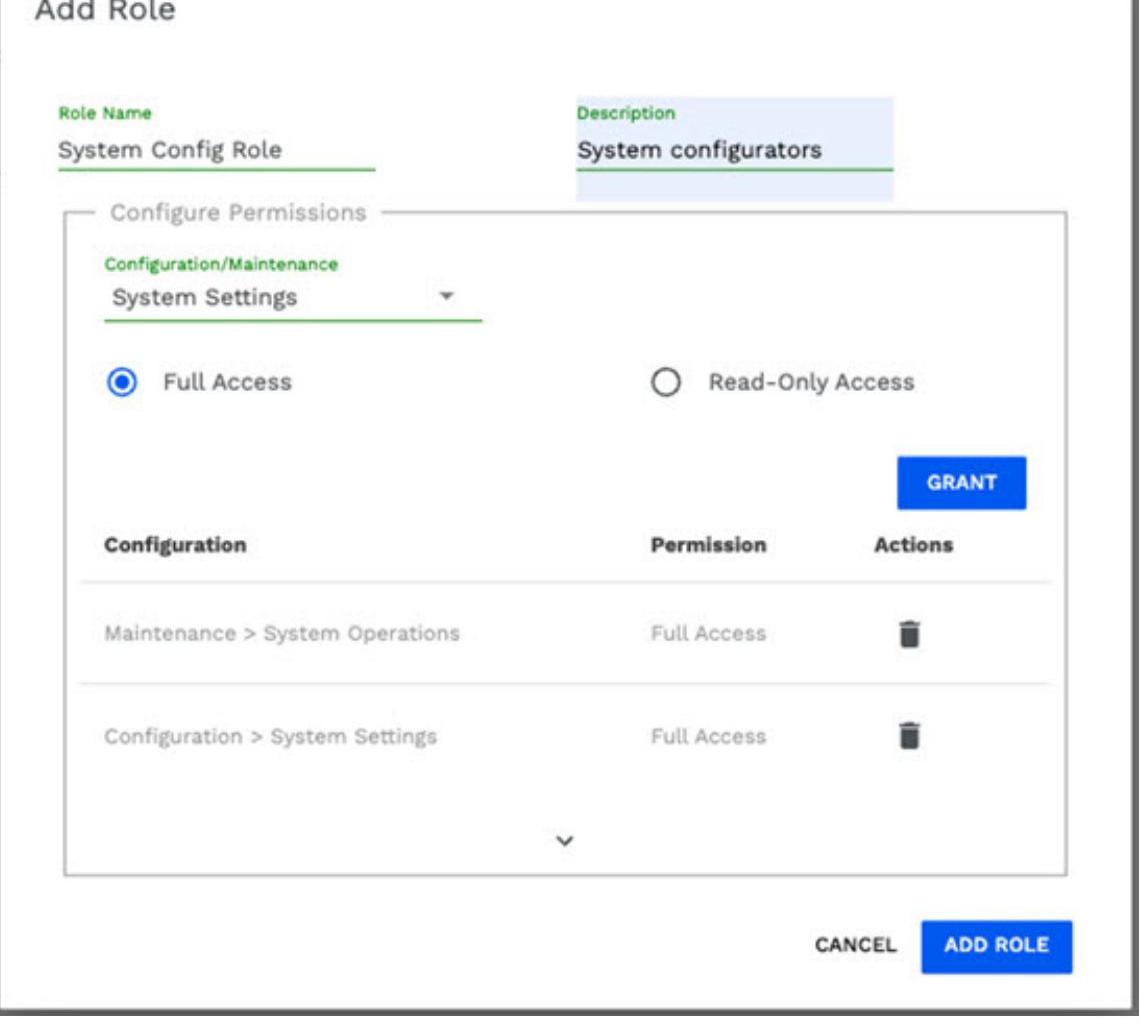 2. Provide the name and description for the "Role".
3. Choose one or more Configuration/Maintenance Operations from the list.
2. Provide the name and description for the "Role".
3. Choose one or more Configuration/Maintenance Operations from the list.
For each selected operation, specify the level of access: 4. Read-Only Access: Users with this permission should view the settings but cannot modify them. 5. Full Access: Users with this permission should both view and modify the settings. 6. Click on "ADD ROLE"
Example of Role Configuration
Consider the following example: The 'System Config Role' has full access for 'System Setting' and 'System Operations'.
- Role Name: "System Config Role"
- Assigned Operations:
- Configuration System Settings: Full Access
- Maintenance System Operation: Full Access
Edit Role
- Click on Access Control > Roles Configuration.

- Select the Role that needs to be modified. Click 'EDIT'.
- Administrator can add or delete permissions for the selected role.
- To add permission, click the dropdown (Configurations/Maintenance) and choose the operations you need.
- To delete a permission, click the relevant 'Actions' icon.
- Click on 'UPDATE ROLE' once done.
NOTE: Role must have at least one permission.
Delete Role
- Click on Access Control -> Roles Configuration.

- Select the role to be deleted and click 'DELETE' to confirm the deletion.
12.15.5 Authorization Rules
Authorization Rules allow administrators to control which roles are assigned to specific Active Directory (AD) groups within CloudFS. By mapping roles to AD groups, the system ensures that users inherit the appropriate permissions defined by those roles. These roles should include different levels of access, such as ReadOnly or Full Access to various CloudFS operations. This is a crucial step in managing user access via SAML SSO, ensuring that AD group members have the correct permissions when accessing the system.
Only authorized Active Directory users should add or edit these authorization rules, providing an extra layer of security. In case the currently logged-in user is not the Bind DN User responsible for managing the directory server, the interface will prompt for SSO credentials of the Bind User.
Add Authorization Rules
- Click on Access Control > Authorization Rules Note:(To configure another Authorization Rule, click Add.

- Select Identity Service's alias name from the list.
- Enter minimum three characters of the AD group name you wish to assign roles.
- Click "Search" to populate the list of matching AD groups.
- The 'Select group' field will get populated with the list of AD groups, Select the desired AD group from the list.
- In the Select Roles dropdown, choose one or more roles to be assigned to the selected group.
- Once all the fields are filled, click "ADD" to save the rule.
Example of Authorization Rules Configuration
Consider the following example:
- Select Identity Service: "Sellsoft AD".
- Search Group Name: sys, click on SEARCH.
- Select Group name: "System Config Grp".
- Select Roles: "System Config Role".
- Click ADD.
This will allow members of the 'System Config Grp' AD group to access CloudFS with the permissions defined under the 'System Config Role'.
Edit Rule
- Click on Access Control -> Authorization Rules.
Authorization Rules Authorization Rules
Group ☐ New ☑ New ☐ New ☐ ☐ ☐ ☐ ☐ ☐ ☐ ☐ ☐ ☐ ☐ ☐ Group ☐ Identity Service ☐ ☐ Role(s) Sellsoft AD Network Config RA ☐ ☐ ☐ ☐ ☐ ☐ ☐ ☐ ☐ ☐ ☐ ☐ ☐ ☐ Group ☐ Identity Service ☐ ☐ Role(s) Sellsoft AD Network Config RA ☐ ☐ ☐ ☐ ☐ ☐ ☐ ☐ ☐ ☐ ☐ ☐ ☐ ☐ ☐ ☐ ☐ ☐ ☐ ☐ ☐ ☐ ☐ ☐ ☐ ☐ ☐ ☐ ☐ ☐ ☐ ☐ ☐ ☐ ☐ ☐ ☐ ☐ ☐ ☐ ☐ ☐ ☐ ☐ ☐ ☐ ☐ ☐ ☐ ☐ ☐ ☐ ☐ ☐ ☐ ☐ ☐ ☐ ☐ ☐ ☐ ☐ ☐ ☐ ☐ ☐ ☐ ☐ ☐ ☐ ☐ ☐ ☐ ☐ ☐ ☐ ☐ ☐ ☐ ☐ ☐ ☐
- Select the Domain from the dropdown, click 'Log In'
- Enter valid AD user details.
- To check the logged-in user, click on 'information' icon, and scroll down to verify logged-in user and role.
- Here the 'user' has been provided 'full access' to 'System Settings' in 'Configuration', only that operation is available.
- Here the 'user' has been provided 'full access' to 'System Operations' in 'Maintenance', that operation is available.
Note: If 'localhost' is selected, provide CloudFS username and password.
12.16 Geofencing Policy
Global organizations must comply with region-specific regulations like GDPR compliance. This often demands strict data residency enforcement and controlled access to sensitive information based on geographic location.
Scenarios where organizations may require geofence:
- One of the defense departments needs to enforce data sovereignty by blocking classified documents from being downloaded on non-US locations.
- A global design firm has offices across different continents. Due to regulatory requirements, they need to restrict their early-stage prototype files from appearing in specific geographic location
- A Pharma company shares their clinical trial data with their labs across regions, but it needs to block these files from appearing in the outsourced labs.
Geofencing Policy allows CloudFS administrators to define fine-grained rules that restrict file or folder access at individual nodes within a CloudFS deployment from a live file system, regardless of the Active Directory permissions and Point-In-Time (PIT) snapshots.
Once a geofencing rule is applied to a specific node, any user accessing the SMB share through that node will be restricted from reading or writing any content protected by the geofencing rule.
The Geofencing Policy rules are managed centrally from the feature in the CloudFS master node WebUI and automatically propagated to all subordinate nodes without requiring system restarts, ensuring real-time enforcement across CloudFS environments.
Note:
- The Geofencing Policy feature supports SMB and S3 protocols, and does not support NFS protocol.
- Geofencing policy rules prevent unauthorized data access initiated by user requests. Administrative operations such as prewarming may allow data to be placed/ cached on the node restricted by geofencing policies. To ensure consistent enforcement, do not prewarm data mentioned in the Geofencing policy rules on the restricted nodes. Even if you prewarm such data on a restricted node, geofencing policy rules will prevent access to that data from restricted node.
The section of a share to be restricted can be defined using geofencing rule. Each Geofence rule is defined for a specific SMB share with the intent to restrict access to a given path pattern from one or more specified CloudFS nodes.
- Nodes that are not specified in the rule can access the share.
- A Geofence rule is not applicable to the owner node of the share, i.e., the node on which this share exists.
- The path pattern is defined using PCRE (Perl-Compatible Regular Expressions), allowing flexible and precise matching.
- By default, the Caseless pattern matching flag is ON. If you want to perform a case-sensitive match, then turn off this flag.
- More Info: You can refer to https://regex101.com/ website and PCRE regex flavor to verify your path patterns against expected restrictions.
- Examples of the path pattern used for restriction: a. Scenario: Restrict access to all content within directory finance of share share .
Description: Need to restrict access to all content within directory finance of share shareY (Full Path: /cloudfs/nodeX/shareY/finance) from CloudFS node nodeA.
Details:
- Restrict access to: All content within directory finance
- Share: share
- Patterns:
- Full Path: /cloudfs/nodeX/shareY/finance
- Relative path: finance/
- Restrict access from: nodeA
Result: With this rule enabled, if a user accesses any files within the finance directory mounted through nodeA, e.g. /nodeA/shareY/finance/report.pdf, then its access will be denied. b. Scenario: Restrict access to only pdf extension files within a directory
Description: Need to restrict access to only pdf extension files within a directory finance of share shareY (Full Path: /cloudfs/nodeX/shareY/finance) from CloudFS node nodeA. Details:
- Restrict access to: All PDF files within directory finance
- Share: share
- Patterns:
- Full Path: /cloudfs/nodeX/shareY/finance
- Relative path: finance/:+.pdf
- Restrict access from: nodeA
Result: With this rule enabled, users will be restricted from accessing all the PDF files within the finance directory. The rest of the files will be accessible. c. More examples:
| Action | Relative Path |
|---|---|
| block single file | finance/sales/sales_Q4.xls |
| block complete folder | finance/sales |
| block file with particular extension | finance/sales/.+.xls |
| block files which have "sales" in between its name | finance/ +sales.+ |
| block files ending with "sales" | finance/ +sales.xls |
| block files having numeric in their name | finance/.+[0+9]+.+ |
| block file names having special characters | finance/.+ +.+ |
| block files having spaces in name | finance/.+1x+[a+xA+5].+ |
| block already hidden files | finance/1..+ |
To configure a Rule over the node(s), ensure that the SMB share for which the rule is applied exists.
Warning:
- Creation or update of Geofencing Rules will restart the SMB server on all CloudFS nodes, which may disrupt active SMB sessions. To minimize the impact, it is recommended to perform this operation during off-hours.
- In SMB Shares, the S3 Interface Access and Manage Share Access features can restrict user access. If access to shared data is limited by either of these features, users will also be restricted from accessing the data via both S3 and SMB protocols.
12.16.1 Add Geofencing Rule
- Login to CloudFS master node web UI using administrator credentials or RBAC user having required access to Geofencing Policy.
- Click Configuration > Geofencing Policy > Geofencing Rules > Add.
- Select the Share on which the restrictions are to be applied. Once selected, the Base Path for the share is displayed.
- Add the file or folder path or the Relative Path Pattern (Pearl Compatible RE Regex). You can also construct and use the path using https://regex101.com/ site.
- Disable the Case-sensitive Pattern Matching toggle if the pattern matching should be case-sensitive.
- In Restrict access on Node(s), select the nodes from which the access is to be restricted.
- Add a unique Description for this Geofencing rule.
- Click Add. The Rule is enabled by default. It can be disabled from Geofencing Rules section.
Note: In a CloudFS deployment, maximum 64 geofence rules can be added, irrespective of their status (enabled / disabled). To add more, delete the disabled rules and replace it with new ones.
Add Geofencing Rule
Define a Geofencing Rule to prevent access to specific files or folders on selected nodes. Enter a path pattern (PCRE regular expression) to define which paths should be restricted.
Warning:This will restart the SMB server on all CloudFS nodes, which may disrupt active SMB sessions. To minimize the impact, it is recommended to perform this operation during off-hours. Do you wish to proceed?
Share richa-share2
Base Path /cloudfs/sub-NEipBv-0/hello/ Relative Path Pattern (PCRE Regex) .exe Caseless Pattern Matching Full Path Pattern /cloudfs/sub-NEipBv-0/hello/.exe
Restrict Access on Node(s) master-KRtWc4
Description Exclude access to all executables
12.16.2 Edit a Rule
Select the rule that you would like to Edit and update the the details as required.
12.16.3 Test a Geofencing Rule
The TEST option enable administrators to validate the rules REGEX against certain file/folder which are intended to be fenced.
- Login to CloudFS master node web UI using administrator credentials or RBAC user having required access to Geofencing Policy.
- Click Geofencing Rule Test.
- Add the Full Path or Folder Path.
- Select the node for which the path is to be restricted in Test for Node.
- Click Test.
- "Found Matching Geofencing Rules" indicates the specified file or path is geofenced from the selected test node, and matching rule(s) are displayed.
- "No matching Geofencing rule(s) found" indicates that there is no Geofence rule for the specified file or path from the selected test node.
12.16.4 Delete a Rule
- Login to CloudFS master node web UI using administrator credentials or RBAC user having required access to Geofencing Policy.
- From the list of Geofence rules, select the rule(s) you want to delete and then click Delete. Click Confirm to finalize the selection and proceed with deletion.

12.16.5 Example of how a Geofence Rule works
Geofencing Rules are defined in Configuration > Geofencing Policy.
Edit Geofencing Rule
Enter a path pattern (PCRE regular expression) to define which paths should be restricted. 1 A Warning:This will restart the SMB server on all CloudFS nodes, which may disrupt active SMB sessions. To minimize the impact, it is recommended to perform this operation during off-hours. Do you wish to proceed?
Share text Base Path /cloudfs/vd-qa-86-gf-m/ Relative Path Pattern (PCRE Regpo) $\rightarrow$ txt Caseless Pattern Matching Full Path Pattern /cloudfs/vd-qa-86-gf-m/.+txt
Restrict Access on Node(s) vd-qa-86-gf-s1, vd-qa-86-gf... Description Block all text files
In Panzura Data Services > Audit, the access denials triggered by geofencing policies are recorded in the PDS Audit report with a status of Failure in the Status column.

12.17 Quota Management
Organizations using distributed file systems like CloudFS often face challenges with uncontrolled file-system consumption by certain users or teams, which can lead to unexpected capacity over usage impacting cost and performance. For example, Big universities may want to limit file system quota for their students.
Quota Management feature empowers organizations to curb the file-system usage by certain user(s) and/or group(s), optimize system usage without overprovisioning, and ensure that critical business units always have the space to operate. This feature helps minimize the need for constant manual oversight while enabling informed decision-making through visibility and alerts. The allocated quota is applied at the user-level or group-level - whichever is less will be displayed, along with current usage. The CloudFS administrators are alerted about quota thresholds when the usage exceeds (not configurable) of the allocated quota.
The Quota Management feature delivers:
- Centralized Control: Administrators can enforce file system quota for intended users and groups from a central point, providing fine-grained control aligned with organizational structures.
- Fair Usage Enforcement: Prevents file system exhaustion caused by disproportionate consumption.
- Capacity Planning: Supports efficient capacity planning based on the number of users & their file system requirements.
- Proactive Monitoring: Admins receive timely alerts as users approach quota limits, allowing proactive management.
- User Self-Visibility: Users get clear visibility into max quota available for their account.
- Audit and Compliance Support: Detailed reporting allows organizations to meet governance and reporting obligations.
- Prompt Access Restriction: Provision to revoke the data access to any user or group without requiring the domain controller (AD) side changes.
12.17.1 Quota Policy
A Quota Policy is configured using CloudFS master node web UI and is enforced across all nodes, regardless of the node to which a user connects. Once a user or group exceeds their allocated quota, all subsequent write operations are blocked, ensuring centralized control and effectively limiting file system usage across the global file system.
- Quota Policies allow administrators to add, modify, or remove quota, helping manage and control the capacity assigned to users or groups. When a quota is fully utilized, further 'write' operations across the file system are blocked.
- Reports allow administrators to download a consolidated view of current usage and allocated quota for users or groups in CSV format and display:
- Total Capacity - The total Managed Capacity available.
- Used Capacity - The amount of capacity currently used across the system.
- Allocated Quota - The capacity allocated to the AD user/group.
If the quota is set for group as well as the user belonging to that group, then quota that is consumed first will be effective. If a user belongs to multiple groups, usage is always accounted to their primary AD group.
To access a Quota Policy:
- Login to CloudFS master node web UI using administrator credentials or RBAC user having required access to Quota management.
- Navigate to Configuration Quota Management.
Add Quota to user/group
- Click Quota Policies > Add and select Apply Quota to User/Group.
- Search User or Group name for which quota is to be set.
- Note: If User/Group is not present in AD, a message is displayed "No result found. Enter a valid AD user or group name and try again." If too many matching Users/Groups found, a message is displayed as "Multiple entries found. Refine the input to obtain a precise result."
- Select intended User/Group displays a list of users and groups.
- Provide the quota value in the Allocate Quota in GB and click Add.
Note: Adding two users with the same AD username is not supported.
To set bulk quota policy to user/group
- Select the Set bulk quota to Users/Groups.
- To download the CSV template, click Download from the NOTE: Download the CSV template, pre-filled with sample data for reference.
- Populate the CSV file with the following details and click Import.
| A | B | C |
|---|---|---|
| User or group ID as per AD | IsGroup = TRUE if the name is Group | Enter Quota value in GB |
- Select the appropriate CSV file and click Open.
Note: To apply the quota policy, ensure the CSV file is in the correct format. If not, the system will return an error: "Invalid Bulk Quota Policy create request."
Important points for CSV import:
- Keep the column headings intact and add the records in CSV file.
- Avoid adding blank cells in the CSV file.
- Column A must contain valid User/Group ID; otherwise, the import will fail with "User/Group not found".
- If the CSV includes invalid entries, only valid records will be processed, along with their applied quota policies.
- The administrators will receive an error: "The CSV import failed", with detailed information and the option to download the error log containing unimported entries.
Edit Quota Policies for user/group
- Click Quota Policies > Users/Groups or use Search User/Group Name field.
- Select a specific User/Group and click Edit. Provide the details mentioned in the table below and click Update.
| Fields | Description |
|---|---|
| Username/ Group Name (read-only) | Displays the Username/ Group Name. |
| Allocated Quota (GB) | Edit the allocated Quota. |
| Used Quota (GB) (read-only) | Refer to the used file-system quota.. |
| Override Quota | Select to disable the quota policy, i.e., provide unlimited quota. |
| Deny Write | Select to revoke data access regardless of quota usage. |
Delete Quota Policies for User(s)/Group(s)
- Click Quota Policies > Select Users/Groups or use Search User/Group Name.
- Select specific User(s)/Group(s) and click Delete.
- A confirmation message is displayed. Click Confirm to delete.
Bulk delete Quota for all Users/Groups
- Click Quota Policies.
- Select checkbox of the first column. This selects all the Users/Groups on that page.
- Click Delete. A confirmation message is displayed.
Important points to note:
- When adding or editing the quota policy, if the allocated quota to a specific User/Group is below the current used capacity, that User/Group's members will not be able to write further across the file system.
- If the Allocated Quota exceeds the Managed Capacity, you will receive a warning: "The Allocated Quota has exceeded the Managed Capacity. Consider increasing it for future usage. Contact Panzura Support for assistance.
- Ensure snapshot synchronization across all nodes to enforce allocated quotas and prevent resource overutilization.
- Contact Panzura Support either by logging in to portal or by sending an email to [email protected] to when you need to update the Quota policy when the CloudFS master node is down.
12.17.2 Report
Reports provide a consolidated view for tracking managed capacity usage and allocated quotas by user or groups.
Quota Management
Quota Policies
Reports
Reports
A consolidated view for tracking capacity usage and allocated quotas per user and / or groups.
Select Report Type
Users Groups Both Users and Groups
The Quota Policies report is exported in CSV format.
13. Maintenance
13.1 Diagnostic Tools
The Panzura node provides diagnostic tools for troubleshooting. To use the node's troubleshooting tools, navigate to the following page: Maintenance > Diagnostics.
13.1.1 Packet captures
Capture packets on the Ethernet ports. Select to capture all packets or restrict the capture to TCP or UDP packets. The captured packets are saved into a file that can be downloaded and sent to Technical Support.
| Packet Capture Option | Description |
|---|---|
| Capture type | Capture selected headers and packets. |
| 1. pkt-capture - Capture TCP and UDP headers and packet. | |
| 2. pkt-capture-tcp - Capture TCP headers and packet. | |
| 3. pkt-capture-header-only - Capture TCP and UDP headers. | |
| 4. pkt-capture-tcp-header-only - Capture TCP headers. | |
| 5. pkt-capture-udp-header-only - Capture UDP headers. | |
| Network Interface Client (LAN) or Client (WAN) | Select whether to collect LAN or WAN packets. |
| Start/Stop | Starts or stops the capture. |
| Download | Downloads a file with the capture results. |
13.1.2 Run Diagnostic tools
Execute network, node-specific, and cloud diagnostic commands. In the Command Type, select a command. Click Run to see a description of parameters for the command and add applicable parameters. If there are no required parameters, clicking Run executes the command. The results are displayed on the screen.
Diagnostic Tool Commands
The following table lists the diagnostic tool commands.
| Command | Description |
|---|---|
| block-mirror-cloud | |
| diag-ad-history | Displays results of the authentication check that is done every 10 minutes. The results are a condensed and analyzed version of the Active Directory history log file. |
| diag-test-dcs | |
| cdiag-report | Displays a data dump. |
| Example: cdiag-report tail | |
| cdiag-switch | Turns cloud diagnostics on or off. Enter on or off. Diagnostics must be on to use the cloud metrics tools. This setting does not survive a reboot. |
| Example: cdiag-switch on | |
| cfg-cloud-signature | |
| cloud-connect-test |
| cloud-runtime-stat | Displays license and connection information based on the cloud license that is loaded, including success, failure, and what ports are open or closed. If the cloud connect is successful, perform cloud-upload-test. |
|---|---|
| Displays runtime statistics. Useful mainly for uploads. The statistics for download are not as useful because pre-fetch is used. For download, failures occur even if status is OK, because the system is looking for future snapshots that do not exist. | |
| cloud-upload-test | Tests the connection to the cloud. |
| diag-ad-config | Displays the status of the Active Directory connection (joined or not). |
| host | |
| layer-four-traceroute | Sends a Layer 4 traceroute command to the specified IP address and optional port number. Example: layer-four-traceroute-gb2 10.3.3.3:443 |
| layer-four-traceroute-gb2 | Sends a Layer 4 traceroute command to the specified IP address and optional port over the GB2 interface (cloud facing). Example: layer-four-traceroute 10.3.3.3:443 |
| local-admin-add | |
| local-admin-del | |
| mark-remote-display | Displays the current setting for remote file marking. |
| mark-remote-enable | Enables remote file marking. |
| nslookup | Obtains information about a host. Example: nslookup host5 |
| pchar | Displays information on bandwidth latency and loss between the node and the specified system. Example: pchar 10.3.4.5 |
| ping | Sends an ICMP ping command to the specified IP address. Example: ping 10.3.4.5 |
| ping-gb2 | Sends an ICMP ping command to the specified IP address over the GB2 interface (cloud facing). Example: ping-gb2 10.3.4.5 |
| repair-ad-config | Reinitialize the SMB/CIFS services. Note that issuing this command results in connection loss. This command does not provide any output. |
| restart-smb-service | Restarts the SMB/CIFS service. |
| restart-grw | Used by Panzura Support. |
| run-cmd | Executes a CLI support-level command. Caution: These commands should be executed only under the direction of Panzura support. Any misuse could void your warranty. Contact Support either by logging in to portal or by sending an email. |
| search-log | Allows to search the system log for the specified keyword. Example: search-log AUDIT |
| show-cfg-error | Displays configuration errors. |
| show-cloud-signature | |
| show-dp-cfg |
| show-dp-data | Used by Panzura Support. |
|---|---|
| show-dp-list | Used by Panzura Support. |
| show-dp-stats | Used by Panzura Support. |
| show-fs-list | Lists all of the local and remote CloudFS file systems. |
| show-fs-snapshot | Lists information about current snapshots. |
| show-interface | Displays interface information. |
| show-inventory | Displays the current PFOS version and the hardware configuration that was originally shipped. |
| show-log-config | Displays information about config changes. |
| show-log-tail | Displays contents of system message logs. Using the EAP capability, the logs can be displayed using the command: show-log-tail /var/log/avquarantine |
| show-malloc-stats | Displays virtual memory allocation. |
| show-pktcap-list | Displays results of any previous packet capture. |
| show-pktcap | Displays the contents of pcap file for the most recent packet capture. |
| show-pktcap-hex | Displays the hex dump of the pcap files for the most recent packet capture. |
| show-pktcap-host | Displays the host information for the most recent packet capture. |
| show-pktcap-icmp | Displays the ICMP information for the most recent packet capture. |
| show-pktcap-list | Displays the list of existing packet captures. |
| show-pktcap-tcp | Displays the TCP information for the most recent packet capture. |
| show-pktcap-udp | Displays the UDP information for the most recent packet capture. |
| show-pool-iostat | Shows current file system stats for read and write IO operations and bandwidth usage. |
| show-pool-list | Displays information about used and free space. Information is the same as in the Dashboard, but in raw form. |
| show-pool-status | Displays information about drive availability and cloud license. |
| show-route | Displays route table information. |
| show-system | Displays system and file information. |
| show-vm-stats | Displays virtual memory status. |
| show-xgrabstate | |
| show-zfs-properties | Used by Panzura Support. |
| show-zone-stats | Used by Panzura Support. |
| show-switchover-log | |
| show-system | Shows a snapshot of the system resources, including load, CPU, and memory usage and the top running processes. |
| smb-add-gcfg | Use this command with the options indicated in this example to allow browsing of snapshots. Example: smb-add-gcfg pz/ _allow browse snapshots=yes After running the command, browse to the -snapshot directory for each share. |
| smb-add-lcfg | |
|---|---|
| smb-clr-gcfg | Used by Panzura Support. |
| smb-clr-lcfg | |
| smb-debug | Used by Panzura Support. |
| smb-dsp-gcfg | Used by Panzura Support. |
| smb-dsp-lcfg | |
| smb-regen-machine-secret | Used by Panzura Support. |
| traceroute | Sends a traceroute command to the specified IP address. Example: traceroute 10.3.3.3 |
| traceroute-gb2 |
13.1.3 Performance Tests
Execute Iperf commands to test network performance. The performance tests measure bandwidth and link quality connections between the node and another device running iperf. The node can run as either an iperf server or client. When the node is running as a client, enter either the host name or IP address of the iperf server in the Parameters field. When the node is running as a server leave the Parameters field empty.
In the Command Type, select the applicable iperf command and click Run to execute the command. The results are displayed on the screen.
Output Examples for Performance Test Tools
This example shows output from client node vmcc92. Diagnostics[57529]: Firewall is temporarily disabled to allow diagnostics operation and shall be enabled when operation is completed automatically.
Client connecting to vmcc94, TCP port 5001
TCP window size: 65.0 KByte (default)
[ 4] local 10.199.10.92 port 45867 connected with 10.199.10.94 port 5001
[ ID] Interval Transfer Bandwidth
[ 4] 0.0- 5.0 sec 636 MBytes 731 Mbits/sec
[ ID] Interval Transfer Bandwidth
[ 4] 5.0-10.0 sec 616 MBytes 698 Mbits/sec
[ ID] Interval Transfer Bandwidth
[ 4] 10.0-15.0 sec 369 MBytes 619 Mbits/sec
[ ID] Interval Transfer Bandwidth
[ 4] 15.0-20.0 sec 312 MBytes 524 Mbits/sec
[ ID] Interval Transfer Bandwidth
[ 4] 20.0-25.0 sec 401 MBytes 673 Mbits/sec
This example shows output in a case where the vmcc94 node is acting as the server.
Diagnostics[46450]: Firewall is temporarily disabled to allow diagnostics operation and shall be enabled when operation is completed automatically.
Server listening on TCP port 5001
TCP window size: 64.0 KByte (default)
[ 5] local 10.199.10.94 port 5001 connected with 10.199.10.92 port 33313
[ ID] Interval Transfer Bandwidth
[ 5] 0.0-120.2 sec 9.09 GBytes 650 Mbits/sec
[ 6] local 10.199.10.94 port 5001 connected with 10.199.10.92 port 45867
[ ID] Interval Transfer Bandwidth
[ 6] 0.0-120.0 sec 9.46 GBytes 677 Mbits/sec
13.1.4 Health Check Diagnostics
The health check diagnostics allows administrators to access the system's status and performance and enables them to take appropriate action:
- Login to CloudFS node web UI using administrator credentials or RBAC user having write access to Node Operations.
- Navigate to Maintenance Diagnostics Tools Health Check Diagnostics.
- Click Run.
HEME
Performance Tests
Measure network performance to and from node.
Health Check Diagnostics
Run health check diagnostic tools.
Health Check Diagnostics
Run various health check diagnostic tools to assess the system's status and performance.
RUH
Output - Health Check ( 18:11:46 | 3-Feb-2026)
| Test | Status | Details |
|---|---|---|
| Hardware Scan | PASSED | All required hardware components (model, CIFS users, iDRAC, CCID, NIC configuration, NIC mode, bandwidth limits) were detected and validated with no issues found. |
| Version and Patches | PASSED | Controller version matches master and all required patches are installed. |
| Bootup | PASSED | Bootup completed successfully. |
| Licenses/Processes | PASSED | All required licenses present and critical processes running. |
| Master/User Snapshots | WARNING | User managed snapshots are not enabled on 'node01-ok0v.panqa- ati.lab'. Windows previous version restore points are affected because of this. Investigate and see if this was left disabled intentionally, fixing if needed. |
| CED Cloud Connect | BACCEE | CED Cloud Connect suecessful |
Health check completed — Download report
| Diagnostic Tools | Output - Health Check ( 01:53:02 | 10-Mar-2026) |
|---|---|---|
| System Operations | ||
| CloudFS Operations | Test | Status Details |
| SMB/NFS Operations | ||
| System Reset and Cleanup | ||
| Master Node Operations | Zpool Status | PASSED Zpool is ONLINE and healthy |
| Global Data Read Write Colla | The controller azure-s is in an unhealthy Global Data Read Write Collaboration state '0'. Read/write collaboration between node04-sw4y and azure-s may be disrupted. | |
| Dirty Cache | PASSED No dirty cache found, all snapshots are uploaded. | |
| Sync | PASSED All Active nodes are reachable, and latency is within an acceptable limit. | |
| Disk Insights | PASSED Disk is healthy. | |
| PDS Audit enabled Check | PASSED PDS Audit is enabled and state is running. | |
| MC Usage Check | PASSED Managed capacity is sufficient. (Available: 2088 GB, Used: 984 GB) | |
| Health check completed - Download report |
The Health Check report displays the health status of the following tests:
| Test | Description | Action to be taken in case of Failure |
|---|---|---|
| Hardware Scan | The hardware scans, detects, and validates all required components. | |
| Components scanned: model, CIFS users, iDRAC, CCID, NIC configuration and mode, and bandwidth limits. | Ask your IT department to check the hardware. | |
| Version and Patches | Controller verifies and matches the installed version and all required patches. | Check the master node version and installed patches; coordinate with support to upgrade to the required version if needed. |
| Bootup | Bootup completion status. | Review rundbg output to confirm successful system boot without critical errors. |
| Licenses/Processes | Verification and running status of all required licenses. | Ensure all required licenses are installed and all critical services/processes are running properly. |
| Master/User Snapshots | Status of Master / User managed snapshots. | Verify that user-managed snapshots are enabled and functioning correctly. |
| CSP Cloud Connect | CSP Cloud connection status. | Run cloud connectivity test to verify CSP access. |
| CSP Cloud Bucket List | CSP Cloud Bucket List retrieval status. | Execute cloud test to validate bucket listing functionality. |
| CSP Cloud Write/Read | CSP Cloud Write/Read upload and download status during expected bandwidth. | Run cloud test with upload/download parameters to validate read and write operations. |
|---|---|---|
| CMP Cloud Connect | CMP Cloud connection status. | Run cloud connectivity test to verify CMP access. |
| CMP Cloud Bucket List | CMP Cloud Bucket List retrieval status. | Execute cloud test to validate bucket listing functionality. |
| CMP Cloud Write/Read | CMP Cloud Write/Read upload and download status during expected bandwidth. | Run cloud test with upload/download parameters to validate read and write operations. |
| AD Join Status | Active Directory connection status for the controller. | Verify Active Directory configuration on the controller and re-join the domain if required. |
| Time Offset w/ NTP | NTP server system time synchronization status. | Confirm NTP server responsiveness and ensure system time synchronization is accurate. |
| Check Drives | Drive check status. | Ask your IT department to check the hardware. |
| Zpool Status | Zpool health status. | Check ZFS pool health and confirm all pools are in ONLINE and healthy state. |
| Global Data Read Write Collaboration | Global Data Read Write Collaboration status. | Verify all the nodes in the ring are active and data access/replication is functioning correctly. |
| Dirty Cache | Snapshot upload and dirty cache status. | Refer the Local Disk Usage section in CloudFS Dashboard Local Status. |
| Sync | Controller reachability and latency status. | Check active node status on the dashboard and confirm snapshot synchronization across all nodes. |
| Disk Insights | Disk health status and insights. | Review disk health, performance, and utilization metrics on the dashboard. |
| PDS Audit-enabled Check | PDS Audit feature status. | PDS Audit feature status. |
| MC Usage Check | Managed Capacity availability and usage status. | [Available only on Master node] Review global MC usage status on the dashboard to ensure licensing and capacity compliance. |
Click Download Report to download a timestamped report of the health check performed.
13.2 System Operations
To monitor the Panzura node's system operations, navigate to the following page Maintenance System Operations. Use the following options to manage master node snapshots, upgrade the node software, download a log file for Panzura Support, or power off the node.
13.2.1 View Active Master snapshots
A master snapshot is a consistency point snapshot for the entire local file system on a node. By default, master snapshots are taken once per week. Because master snapshots can consume significant IO resources, Panzura provides the ability to modify the master snapshot schedule.
This section lists the existing active master snapshots, including the snapshot number that is assigned when the snapshot is taken, the time the snapshot was created, how long it took to complete, and the size of the snapshot file.
13.2.2 Generate Master Snapshot
Use this section to modify the schedule for the master snapshot.
Note: The exact time that the first snapshot occurs depends on the configured interval between snapshots. For example, if the interval is 15 minutes, the first snapshot will occur 15 minutes after the scheduled time.
To modify the schedule for a master snapshot:
- Select a day of the week and time from the drop-down lists.
- Select a recurrence interval (from 1-4 weeks)
- Choose one of the following actions:
- Save to save the configuration and start the snapshot schedule.
- Generate a Master Snapshot Now to order a snapshot on demand.
13.2.3 Upgrade
The node can be upgraded manually to a specific image or patch. New OS images and patches are available from Panzura support. For information on enabling automated updates, see the next entry in this table.
Select an option (Image or Patch), click Choose File, and select the file to upload. When the upload is complete, click Upgrade. Contact Panzura Support either by logging in to portal or by sending an email to [email protected].
13.2.4 Reboot
To reboot with an image, select the image and click Reboot.
13.2.5 Support Log
To generate a packet capture on the Maintenance Diagnostics page, click Download Support Log to download and save a copy of the log file to your desktop (file name panzura.support). If requested, send this log file to Panzura Support. Click this button to save the capture and then click Save to save the file to your local system and send it to Panzura. See Diagnostic Tools for instructions on taking packet captures.
Contact Panzura Support either by logging in to portal or by sending an email to [email protected].
13.2.6 MIB File
To download all Panzura MIB files, click Download.
13.2.7 System Configuration
To download CloudFS configuration, click Generate.
13.2.8 Power Off
Halts the node and turns the power off.
13.3 ICAP Operations
Internet Content Adaptation Protocol (ICAP) is a standard or URL modification, web cache management, and anti-virus scanning of URL, http posts, and file server files. The node uses ICAP as a client to send file content to antivirus servers for virus scanning.
Use the ICAP Un-Quarantine page to determine whether an ICAP server responds, to quarantine files if that has not been done by the ICAP server, and to release quarantine as needed.
Important ICAP Notes:
The following apply to the ICAP operations options:
- This feature is available only if the ICAP license is installed.
- Specify the ICAP parameters on the License Manager page.
- If you have specified an ICAP server on the License Manager page, the IP address of the server is filled in automatically on the ICAP page.
- To probe another server in this page, enter an IP address and click Probe Server. However, the address you enter is not saved.
- Results of the server probe are displayed in a pop-up window.
- Quarantining of files is typically done by the ICAP server. If needed, manually quarantine or un-quarantine files in the ICAP Un-Quarantine page.
- Any viruses that are found are listed in /var/log/avquarantine, which is accessible on the Maintenance Diagnostics page.
To access ICAP operations options, navigate to the following page Maintenance ICAP Operations. The following table describes the node's diagnostic tools.
| Packet Capture Option | Description |
|---|---|
| ICAP Server Test | |
| Test Communications | Enter the IP address or hostname of an ICAP server and click Test Communication to verify that the node can communicate with the server. |
| ICAP Log | |
| ICAP Log | Displays the ICAP log. |
| ICAP File Quarantine | File path and name Specify the path of the file to quarantine or un-quarantine. |
| File path and name | Quarantine the specified file. |
| Quarantine | Remove quarantine status from the specified file. |
| Un-Quarantine | Display the current quarantine status. |
| Quarantine Status |
13.3.1 ICAP Options
To use ICAP, specify the following ICAP parameters on the Configuration > Licenses Manager page under AS-ICAP. See License Manager. The following table lists the ICAP options.
| Option | Description |
|---|---|
| Port | The default ICAP port is 1344. Change the value if the ICAP server is listening on a different port. |
| Service | ICAP service name. This is ignored by most ICAP servers; however, some vendors require specific values. avscan is the most common service name. |
| include-files | Comma-separated list of of glob based file paths that will be scanned. Use * as a wildcard. |
| exclude-files | Comma-separated list of of glob based file paths that will not be scanned. Use * as a wildcard. |
| scan-on-read | Scan files when they are open for reading. |
| scan-on-write | Scan files when they are closed following write operation. |
| denyonerror | If no scanner is available or some system error has occurred, assume that the content is suspicious and deny client access. |
| allow206 | Not currently supported. |
13.4 ICAP Operations
The Internet Content Adaptation Protocol (ICAP) license uses an ICAP-capable enterprise-class virus scanner to automatically scan files with the latest virus definitions based on ICAP. Actions include the ability to block the file from being accessed, logging the detection event, and quarantining the file. If a file was previously scanned, it is not rescanned unless the virus signature information has changed, the cloud node has rebooted, or the filename, contents or path have changed.
To view the logs associated with ICAP quarantine, select Maintenance Diagnostics, and use the Diagnostic Tools command. See ICAP Operations for information on managing operations with the ICAP server.
The following settings are available to edit an ICAP license in the License Manager section. For more information, see ICAP Best Practices. The following table describes the ICAP settings.
| ICAP Setting | Description |
|---|---|
| Port | Specify the port number used by the antivirus scanners. All scanners must use the same port. The industry standard port assignment for ICAP assigned by IANA is 1344 (default). |
| scan-on-write | Specify whether to scan files when they are saved or closed (default no). |
| Exclude Files | Specify patterns to explicitly identify files not to be scanned. Example: Enter *.pdf to exclude files with the pdf suffix from the scans. |
| Host** | Specify the IP address of the anti-virus scanner, using commas to separate multiple scanners. The node load balances across the scanners in a roundrobin fashion. All scanners must be synchronized with identical virus definitions and configured identically. |
| allow206 | Not currently supported. |
| Include Files | Specify patterns to identify the files to be scanned. The default is '*' which indicates that all files are scanned. Example: Enter *.exe, *.docx to scan only files with the exe or docx suffix. |
| scan-on-read | Specify whether to scan files when they are open for reading (default no). |
| Service | Specify the antivirus scanner ICAP service name. Most scanners ignore this parameter. avscan is the recommended default. |
| Deny on Error | Specify whether to assume content is suspicious and deny read access if the av scanner is non-responsive for any reason and no other scanners are available (default yes). Applies only to scans done on read operations. Deny on Error will not prevent a write to a disk if the file was not scanned. |
13.5 CloudFS Operations
On the master node, go to Maintenance CloudFS Operations to view information about the CloudFS. This section displays a list of the current CloudFS hosts and allows to pause or resume Remote FS Sync. Remote FS Sync determines whether each node receives snapshots from other nodes in the CloudFS. By default, Remote FS Sync runs everywhere. When the Resume button is visible, Remote FS Sync is currently paused, and snapshots are not being received from the selected node to this node. Click Resume to start running. Search the list, choose the number of entries to display per page, and use the paging controls to page through the list.
13.5.1 CloudFS Browser
Explore the folders and files on the nodes in the CloudFS deployment.
- Click a folder in the list to explore its contents. The path is shown at the top of the list.
- Click a file to display information about the file, including path, antivirus status, creation and modification details, and cache.
- Click the arrow above the list to return to the parent folder.
CloudFS Operations

13.5.2 Secure Erase
This functionality is available only if the License for Secure Erase feature is installed. Go to License Manager > Installed License Modules and confirm the license for Secure Erase license.
Secure Erase allows you to delete a file or folder in such a way that the contents cannot be restored, even using the most advanced technology available.
Secure Erase removes all versions of specified files and folders, including the associated objects stored in the cloud. User managed snapshots containing copies of the files and folders are explicitly noted in the Secure Erase output and not erased. This enables the administrator to take the appropriate action for the snapshots within the context of their environment. The snapshots will age out according to the settings defined in User Managed Snapshot settings. See System Operations.
- Specify the file or directory name to remove.
- Select a date for deletion, or click Now for immediate deletion.
- Click Run to activate the delete operation.
- The Schedule Files/Directories list shows when scheduled items will be deleted, and the table at the bottom of the page lists the files that have already been deleted.
- Click Download Report to download a report of the actions taken by Secure Erase. After the report is downloaded, click Clear Reports to erase all the report contents from the system.
13.5.3 NT ACL Tool
Panzura now supports an Apply NT ACL (Windows Permissions) change tool that enables changing ACLs (Access Control Lists) recursively to a large CloudFS filesystem with faster than LAN (SMB client) performance. To locate the tool, go to Maintenance CloudFS Operations NT ACL Tool on the CloudFS WebUI. For more details, refer to Apply NT ACL Tool.
13.6 SMB/NFS Operations
To view a list of currently connected SMB clients or to restart the NFS service, navigate to the following page: Maintenance SMB/NFS Operations.
13.6.1 SMB Clients
View the list of currently connected SMB clients.
13.6.2 SMB Open Files
View the list of currently connected SMB open files.
13.6.3 NFS
Click Restart to restart the NFS service after changing the NFS configuration. Note: This option terminates all current NFS sessions.
13.6.4 File Lock Release
In collaborative environments, file(s) may remain locked if the user holding the lock is offline. In such case, the file(s) cannot be claimed by other users from that node or any other node in that CloudFS ring. To maintain uninterrupted collaboration, CloudFS provides a mechanism to transfer control of such files using the File Lock Release.
When a lock is released, ownership of the file is reclaimed by the file owner, and the file becomes accessible from all other nodes. The File Lock Release option is available on both master and subordinate nodes that are in an active state. The master node releases lock for file(s) across the CloudFS deployment and the subordinate node releases lock only for any file belonging to the shares owned by them.
Diagnostic Tools System Operations CloudFS Operations SMB/NFS Operations System Reset and Cleanup Master Node Operations
SMB Clients View currently connected SMB clients.
NFS Restart NFS Service
File Lock Release Release file lock
File Lock Release Reclaim control of files locked by offline users
RELEASE SINGLE FILE LOCK RELEASE MULTIPLE FILE LOCK
File path \panqa-atl.lab\dfs_namespace\test\cache_csv_huge_001.csv
File Lock Release History
| Time | Mode | Status | Input |
|---|---|---|---|
| 10 Mar 2026, 11:56 | Single File | Success | \panqa-at... |
| 10 Mar 2026, 11:54 | Multiple Files | Partial Success | CloudFS-FI... |
| 10 Mar 2026, 11:53 | Multiple Files | Success | CloudFS-FI... |
| 10 Mar 2026, 11:51 | Multiple Files | Failed | CloudFS-FI... |
| 10 Mar 2026, 11:50 | Single File | Success | \ami-site... |
Steps to Release a File Lock
- Log in to the CloudFS master node web UI using administrator credentials or an RBAC user with write access to SMB/NFS Operations.
- Go to Maintenance > SMB/NFS Operations > File Lock Release.
- To release a single file lock, select Release Single File Lock tab and enter the absolute file path for which the lock must be released.
- Click Release.
Paths for reference: \fileserverS1.domain.com\shared_documents\projects\project_files\document.docx \company. Local\dfs_root\finance\reports\quarterly_report.xlsx For example, File Owner: node_1 Data Owner: node_2
Consider the share panzura_hr at Share Target Path node_1, where the file allemployee.xlsx resides. If the file is locked by user_2 accessing via node_2, who is currently offline or unavailable, users across all nodes in the CloudFS ring will be unable to access the file. In such cases, the CloudFS administrator can log in to the File Owner's web UI to release the file lock or ownership of allemployee.xlsx.
Examples of file path:
- \node_1\panzura_hr\allemployee.xlsx
- \domain_name\dfs_name_space\share_1\allemployee.xlsx
- \node_1.<fqdn>.com\panzura_engg\allemployee.xlsx
Note: The placeholder . . . . indicates that the file may exist at any level of the directory hierarchy. To release multiple files lock To release the locks of multiple files, select Release Multiple File Lock tab, and click Import to upload the file. The selected file is uploaded and the release process starts.
Reference Template can be leveraged to create a .CSV file with the list of files for which the lock is to be released. Maximum 1000 files can be listed in the .CSV file.
Note: The same steps can be performed from a subordinate node to release the file locks for any file belonging to the shares owned by them.
Diagnostic Tools System Operations CloudFS Operations SMB/NFS Operations System Reset and Cleanup
Master Node Operations

File Lock Release History

File Lock Release History
The File Lock Release History table shows the status of all file release operations and upto 5 latest reports will be displayed. Click Download Report to view detailed information.
Auditing File Lock Operations
File lock release operations are audited. To view them, navigate to Notifications > Audit Trail.
13.7 System Reset and Cleanup
To reset and clean up the system, take snapshots, or recover using snapshots, navigate to the following page: Maintenance > System Reset and Cleanup.
Caution: Contact Panzura Support either by logging in to portal or by sending an email to [email protected] before performing any of the operations in this section.
13.7.1 Restore Node from Cloud
Restores the file system on this node with the file system in the cloud storage. The node reboots and then recovers the metadata from the cloud storage backend. You can choose to recover to the most current state of the file system, or to recover to the state of the file system as captured in a specific snapshot. See Snapshot Settings for snapshot names.
When a node is prepared for disaster (by following the disaster recovery procedure), the screenshot is displayed on the node. If the intention is to restore the local file system from the cloud backend, then the restore local file system action should be performed only when the following message is displayed. If the message is not displayed on a new node that has been configured for disaster recovery, contact Panzura Support either by logging in to portal or by sending an email to [email protected].
Filesystem already exists in CloudFL. Please perform Disaster Recovery now by clicking HERE. Otherwise, please contact Panzura support.
13.7.2 Delete Filesystem and Clear Stats
Stops all read/write operations on the node, purges all data from the node, and clears all reporting statistics. The system reboots, stopping all read-write operations.
13.7.3 Reset to Factory Settings
Resets all system values to factory defaults. Stops all read/write operations on the node, purges all data from the node, clears all reporting statistics, deletes the configuration information, and resets the system to factory defaults.
13.7.4 Repurpose Node
Makes the node available for other uses after it has been removed from a high availability configuration. This process removes the cloud node ID (CCID). After clicking the button to repurpose the node, contact Panzura support either by logging in to portal or by sending an email for a new license to operate the node.
13.8 Master Node Operations
To manage passwords, generate a configuration file, or decommission a node, navigate to the following page: Maintenance > Master Node Operations Note: These options are available on the master node.
13.8.1 Change Password for Admin
Enter and confirm the new password for the administrative user and click Save Password. Default is admin.
13.8.2 Change Password for Restricted Users
Enter and confirm the new password for the user account and click Save Password. Default is user.
13.8.3 Change the password for the disk drive locking
If you have a physical node that was shipped with disk encryption enabled, use this setting to change the password for locking and unlocking disks. Enter the current password (default is Panzura1*DE) and then enter and confirm a new password.
13.8.4 Generate Configuration File
Causes the Master node to create a new configuration file that the Subordinate nodes can synchronize to.
13.8.5 Ring Status Management
In CloudFS deployments, nodes need to be deactivated (graceful shutdown) due to scheduled maintenance or are unavailable due to catastrophic conditions (ungraceful shutdown) like a power outage, or other transient conditions like a hurricane impacting the CloudFS node availability for a few long hours or days. This leads to the involvement of the Panzura Support team to transfer the ownership/lock of the files owned by such a node to some other CloudFS node/s, where the users can resume their work. Depending on the volume and nature of data to be migrated, this procedure takes a longer time and is error prone.
Likewise, in CloudFS deployments, nodes need to be decommissioned (permanently removed) for reasons such as hardware lifecycle, relocation, efficiency improvements, and cost optimization.
The Ring Status Management feature provides CloudFS administrators with the ability to deactivate (bring the node down), activate, and decommission individual nodes from master's web UI, providing seamless visibility across the CloudFS ring status.
Deactivate: It enables CloudFS administrators to bring a node down, typically for a few days to a few weeks, allowing active users to work on data presented by this node to immediately and seamlessly resume their work by connecting to any other node in the CloudFS ring. This feature supports both graceful and ungraceful shutdowns, such as a power failure or a system crash.
Activate: It enables CloudFS administrators to bring the deactivated node online. Decommission: It enables CloudFS administrators to permanently remove a node from the CloudFS ring, allowing users to continue functioning through other nodes in the CloudFS ring.
This interface allows to manage all the subordinate nodes (except nodes with file ownership) from the master node web UI. This doesn't include managing actions for master, LHA, and GHA nodes.
Accessing Ring Status Management
- Login to CloudFS master node web UI using administrator credentials or RBAC user having write access to Master Node Operations.
- Navigate to Maintenance Master Node Operations Ring Status Management to view the list of nodes in the CloudFS ring, their roles, status, and actions that can be performed on each node, as mentioned below.
The following table describes the status and possible actions for the subordinate nodes.
| Status | Description | Actions |
|---|---|---|
| Online | The node is active and healthy. | Deactivate |
| Decommission | ||
| Offline | The node is shutdown or not reachable. | Deactivate |
| Decommission | ||
| Deactivated | The node is temporarily brought down for | |
| maintenance activities or to avoid impact of | ||
| natural calamaties like hurricane, typically from | ||
| few days to few weeks. | Activate | |
| Decommission | ||
| Decommissioned | The node is permanently removed from the ring | |
| and is no longer available. | No action needed. |
HOME MAINTENANCE S
Diagnostic Tools System Operations CloudFS Operations SMB/NFS Operations System Reset and Cleanup Master Node Operations
| Ring Status Management | Search | ||
|---|---|---|---|
| To monitor and manage the health and status of the node. | |||
| Node 0 | Role 0 | Status 0 | Actions |
| pb-m-vip | Master | Online | |
| pb-gha | GHA | Online | |
| pb-m-lha | LHA (pb-m-vip) | Online | |
| pb-s2 | Subordinate | Online | Decommission |
| pb-s2-lha | LHA (pb-s2) | Online | Deactivate |
| pb-s3-vip | Subordinate | Online | |
| pb-s3-lha | LHA (pb-s3-vip) | Online | |
| pb-s1 | Subordinate | Deactivated | |
Note:
- All the above actions may take few minutes to complete, and the live status of the ring is updated every few seconds.
- A single action can be performed on a node across the ring at any given time.
Deactivate
Following are the prerequisites to deactivate a node: a. To deactivate a subordinate node that holds both file and data ownership, it is recommended to copy the file to the other nodes in the CloudFS ring. b. If the file-owner node is to be deactivated, set up an LHA node (if not already paired), perform the failover. c. If the subordinate node is paired with an LHA node in the same region (with or without a shared VIP), gracefully shut down the LHA node first and then deactivate the subordinate node. d. To deactivate a subordinate node paired with an LHA node in a different region, use the failover mechanism.
Steps to deactivate the node:
- Login to CloudFS master node web UI using administrator credentials or RBAC user having write access to Master Node Operations.
- Navigate to Maintenance Master Node Operations Ring Status Management.
- Select the subordinate node from the list and click Deactivate.
Deactivate
Do you want to proceed with deactivating node node02-20na?

In case if the initial node status is Online and it is Deactivated, all the services are gracefully stopped and node is brought down in the following sequence:
- New SMB connections are blocked.
- All active oplocks/leases are recalled - clients flush any pending writes.
- System waits for client acknowledgements (up to seconds per SMB2 specification).
- The remaining sessions are disconnected.
- Full client access is disabled.
In case if the initial node status is Offline due to a power outage or system failure, it can still be Deactivated. Note: After a node is deactivated in a CloudFS cluster, there may be a brief delay before the dashboard reflects the updated status. During this period, the dashboard may continue to show the node as Up for approximately minutes, even though the node has already been deactivated. The dashboard updates to show the node as Down once the node is powered off.
Activate
It allows CloudFS administrator to bring the deactivated node online.
- Login to CloudFS master node web UI using administrator credentials or RBAC user having write access to Master Node Operations.
- Navigate to Maintenance Master Node Operations Ring Status Management.
- Select the subordinate node from the list and click Activate and power on the node.
The CloudFS administrator can log in to the web UI of the activated node to monitor its bootup process, as shown in the image. The alert is generated when the node is successfully activated.
Node is Booting Up
\I INFO: The node is completing boot-up steps. It can take a long if cloud connectivity is affected or the node needs to
catch-up with snapshots in the cloud. To troubleshoot, run the following commands from the Diagnostic Tools on the
Maintenance page.
    - Cloud-connect-test
    - Cloud-upload-test 4M 5
Progress:
Searching for an active cloud license... Done Checking for encryption file... Done Retrieving licenses... Done Importing the file system... Done Datapath ensuring local filesystem is synced with cloud... Done Waiting for FS command to configure the controller list... In Progress [Node rejoin workflow] Checking node state... In Progress [Node rejoin workflow] Awaiting to be marked up by master... In Progress
Note:
- When node is Online and is deactivated, there is no risk of losing dirty cache as it automatically synchronizes it's snapshots to cloud before graceful shutdown.
- The node is not marked online until it completes syncing its peer snapshots, with a delta of five snapshots per node.
- When the node is brought back online after an ungraceful shutdown, it saves any dirty data from its local cache that couldn't be uploaded to the cloud into the /cloudfs/<deactivated_node_fs>/lost+found directory. To share the protected user data saved in the /cloudfs/<deactivated_node_fs>/lost+found folder, the administrator must access it by mounting the /cloudfs/{filesystem_name} share on a Windows host. If required, this data can then be shared with the respective end users to allow them to recover their files.
Decommission
Following are the prerequisites to decommission a node in a managed way:
- All the snapshots of the node to be decommissioned are uploaded on the cloud and in sync, the decommissioned node should be in a healthy state, and no dirty cache should be found.
- Conduct a basic health check on both the source and destination lessor node, including dirty cache and snapshot synchronization status.
- It is recommended to decommission nodes one at a time, as the process consumes resources; however, multiple nodes can be decommissioned simultaneously if needed.
- If the file-owner node without LHA node is to be decommissioned, copy the local data to another node before decommissioning it.
- Before decommissioning an active node with a configured Standby (Local HA) node, the HA pair must be unpaired.
- Perform the share migration from the node to be decommissioned if required.
If the node is already in a non-functional state (offline) due to a power outage or system failure, it can still be forcibly decommissioned by skipping the snapshot sync-up.
Once the decommission is triggered, it disables the client's read-write access to the node and mark it as "Decommissioned". At the same time, each file-owner node prepares a list of data owned by the decommissioning node, followed by the lock migration running in the background. During this process, CloudFS dynamically adjusts thread allocation for lock migration based on real-time system resource usage (CPU, memory, disk space, and snapshot activity). This ensures optimal performance, balanced workload distribution, and improved system stability throughout the decommission process.
There is an option available to Shut down the node once the decommission is complete. If not selected, one can confirm whether it needs to be up and running by checking the file path- /cloudfs/.eng/decom.
Forced Decommission
The system uploads a decommission marker to cloud storage during forced decommission. On every subsequent boot, the node checks for this marker and, if found, automatically enters maintenance mode instead of rejoining the ring. This ensures a forcefully decommissioned node can never accidentally rejoin and disrupt the cluster.
Decommission the subordinate node:
- Login to CloudFS master node web UI using administrator credentials or RBAC user having write access to Master Node Operations.
- Navigate to Maintenance Master Node Operations Ring Status Management.
- Select the subordinate node from the list and click Decommission.
- When decommissioning a node that has not yet completed uploading it's snapshots to the cloud, select the option Skip snapshot sync-up and shut down node.
- Click confirm. The system will complete the forced decommission and automatically shut down the node, disabling all client access and stopping all services.
Decommission the master node:
- Login to the CloudFS subordinate node's web UI using administrator credentials or RBAC user having write access to Configuration.
- Change the role of the subordinate node to master by navigating to Configuration -> System Settings -> Configuration mode. Select the "master" option and click Save and logout from the node.
- Login to CloudFS master node web UI using administrator credentials or RBAC user having write access to Configuration.
- Change the role of the master node to subordinate by navigating to Configuration -> System Settings -> Configuration mode. Select the "subordinate" option and click Save.
- Ensure the new master node is known to all the subordinates or is recognized by all the subordinates.
- Login to new master node web UI using administrator credentials or RBAC user having write access to Master Node Operations.
- Navigate to Maintenance Master Node Operations Ring Status Management.
- Select the subordinate node (which was master earlier) from the list and click Decommission.
- Once the decommission process is triggered, lock migration will be running in the background.
Decommission Node
This will disable client's read and write access to the node92 zona node and mark it for decommission. Do you want to prevent? $\square$ Shut down node automatically when complete CANCEL COME NOW
Decommission an active node associated with LHA:
To decommission a subordinate node that is part of an LHA pair with a shared VIP configuration, first break virtual IP (VIP) configuration for HA local and active node pair, remove the pair from the HA configuration and then initiate the decommission.
- Login to CloudFS master node web UI using administrator credentials or RBAC user having write access to Master Node Operations.
- To decouple the standby node associated with that node, navigate to Configuration Actions. Select the pair and delete the configuration. Power off the LHA node once it is decoupled.
- Navigate to Maintenance Master Node Operations Ring Status Management.
- Select the subordinate node from the list and click Decommission.
13.8.6 Master Active Cleanup
- Login to CloudFS master node web UI using administrator credentials or RBAC user having write access to Master Node Operations.
- Navigate to Maintenance Master Node Operations Master Active Cleanup.
13.8.7 Prewarm Provision
The Prewarm Provision feature allows CloudFS administrators to ensure data is pre-populated on the node from the cloud before users access it. This can be used for HA failover preparation or to pre-populate data for large projects. This option is available on the master node.
Note:
- CloudFS administrator has an option of Evict Existing Cache (excluding pinned) if existing files in the cache of the node(s) are to be evicted while prewarming, in case the prewarming size is more than the available free space. We recommend using this option with caution, as there will be latency for accessing the evicted files. If selected, the user will be asked to provide consent.
- Geofencing rules enforced through SMB (Samba) prevent unauthorized data access initiated by user requests. However, administrative operations such as prewarming may bypass these restrictions and allow data to be placed/cached on the node even if it would otherwise be restricted by geofencing policies. To ensure consistent enforcement, do not prewarm data mentioned in the Geofencing rules on the restricted nodes. Even if you prewarm such data on a restricted node, geofencing rules will prevent access to the same. To ensure consistent enforcement, equivalent filtering should be applied to prewarming operations.
Prerequisite
Before initiating a prewarm job, please ensure that:
- Snapshots are synced between the node(s) to be prewarmed and the node hosting the share. This can be checked on the Web UI Dashboard. In case the snapshots are not in sync, then prewarm will be able to download only the files that are in the latest local snapshot.
- There is sufficient PRC cache space. Files prefetching may fail silently if the available space is inadequate.
Note : Prewarming small files (files ) requires more space than their actual size.
Prewarm
There are two ways for a CloudFS administrator to perform prewarm:
- Prewarm Directories: This allows users to select the directories to prewarm as per the selected criteria by providing the "Directory" name. e.g., prewarm a directory with subdirectories, files modified within days, with or without cache eviction.

- Prewarm File List: It allows users to prewarm the list of files with or without cache eviction.

To Prewarm:
- Login to CloudFS master node web UI using administrator credentials or RBAC user having write access to Master Node Operations.
- Navigate to Maintenance Master Node Operations Prewarm Provision.
- Select Nodes from the list of nodes (including standby nodes) as applicable.
- Add a Description for this job.
- To Prewarm Directories:
a. Select Prewarm Directories tab.
b. Select Share from the list of shares.
c. Provide UNC / DFS / comma-separated CFS Directory Path(s) under Share for directories that you want to prewarm. Examples:
CFS Path: "acme_hr" is a share containing multiple directories of which, you want to prewarm two directories namely year2025, year2026 then provide /year2025, /year2026. If you want to include files that are at the root level, then provide .
UNC Path:
10.xx.yy.xx\cloudfs\dir\file.txt DFS Path:
DONAIN dfs cloudfs dir file.txt
d. Select Include Subdirectories if you want to include them in the prewarm process. This will prewarm any subdirectories inside year2025 & year2026. e. Specify the count of the Files Modified Within (Days). Files modified during this period are included in the list of files prepopulated for the prewarm provision. f. Select Evict Existing Cache as needed. g. Select Include Alternate Data Stream to prewarm Alternate Data Streams (ADS) associated with files. ADS are additional streams of data associated with a file, commonly used on Windows to store metadata or other file-related information without changing the file's primary content. This option lets the customer choose whether prewarm should proactively pull ADS content into the cache along with the primary stream, ensuring that ADS-dependent workflows also receive the full performance benefit of the warm cache. h. Click Submit. This initiates a prewarming job, and its progress can be viewed in the Prewarm Job Status table. i. If you want to generate a list of files, click Generate File List. This initiates a job to generate a list of files, and its progress can be viewed in the Prewarm Job Status table. Click the Download icon to download the following report as applicable:
- Success: prewarm job 2 node01 date.csv file is generated on successfully completion of the job. It contains the list of files to be prewarmed based on the specified criteria set in this feature. This can be used to confirm the list of files and refine it further as needed. Example: List only files modified within last 7 days. The final version of this file can be used as an input to the Prewarm File List section.
- Partial Successful or Failure: status file.csv is generated when this job execution is partially successful or failure. You can take appropriate action and regenerate the list.
- To Prewarm File List: a. Select Prewarm File List tab. b. Create a .csv file with the following example path in the file.
Example: CloudFS Path: /cloudfs/PB-M/enq/test_data_hierarchy/100_GB/file_000001.dat UNC Path: DFS Path: DOMAIN dfs cloudfs dir file.txt The system automatically converts UNC/DFS paths to CloudFS paths. c. Or select a .csv file which is generated previously from the Prewarm directories Generate File List and then click Open. d. Select Evict Existing Cache as needed. e. Click Submit. This initiates a prewarming job, and its progress can be viewed in the Prewarm Job Status table. Click the Download icon to download a status report.
Schedule a Prewarm Job
CloudFS administrators can schedule data prewarm jobs using REST APIs:
- Schedule via directory paths: POST /pz/cfs/api/v1/prewarm/start/directorypaths
- Schedule via file list: POST /pz/cfs/api/v1/prewarm/start/uploadfilelist
- Schedule via file list generation: POST /pz/cfs/api/v1/prewarm/generatefilelist
For scheduling a job, set the scheduled_on parameter in the payload which accepts epoch time. After the scheduled job REST API is triggered, It will appear in the Prewarm Job Status with status as "Scheduled". The job will automatically execute at the scheduled time and update its status (In Progress Completed / Partial Success / Failed).
Prewarm Job Status
The Prewarm Job Status table displays the node-wise status of executed prewarm jobs. Click the corresponding prewarm job to view detailed information.
NAME
Diagnostic Tools System Operations CloudFS Operations SMB/NFS Operations System Reset and Cleanup Master Node Operations
RELIEVING
SELECT FILE
Evict Existing Cache
Prewarm Job Details
Job ID: Node Name: Submitted By: Started On: Scheduled On: Status: CFS Share: Directories: Modified Files Within Days: Include Subdirectories: Evict Existing Cache: Include Alternate Data Stream: File Uploaded: Generate File List: Description: Message: Completed On:
2
pb-az-s3 admin 11:24:06 | 28-Jul-2026 Completed hpv-s3 0 Yes No Yes Yes 11:58:32 | 28-Jul-2026
CLOSE
Type of status:
- Completed: Prewarm or generation of list is successful. Check prewarm_job_2_node01_date.csv for the result of Generate File List.
- Partial Success: After the job is finished, a few files were prewarmed or generated a list of file, whereas the remaining reflected an error. Check the status_file.csv for more details.
- Cancelled: The prewarm job of the selected node is successfully cancelled. This status may take a moment to reflect on the UI.
- Failed: If any node is unreachable or unable to prewarm the files mentioned in the Prewarm File list, or if all the file paths are incorrect.
Cancel prewarming job
Select the specific in-progress prewarming job(s) and click Cancel. It will halt prewarming, and the prewarmed files up to that point will remain available on the specific node(s). All actions will be seen on the Audit Trail.
Note:
- To generate the list of files to be prewarmed across multiple nodes (ensuring the nodes are in sync), select a single node and Generate File List. The generated list ( prewarm_job_2_node01_date.csv) can be provided as an input to the prewarm file list job.
- The generated list ( prewarm_job_2_node01_date.csv ) columns file path and file size help administrators estimate cache impact and make informed decisions before submitting a prewarm job.
- It is advisable to run the prewarm job outside of regular business hours.
- For a node which is to be deactivated on which prewarm job is currently running, it is recommended to cancel the in-progress Prewarm job (if any) and then deactivate the node.
- For a node which is to be decommissioned and a prewarm job is currently running, it is recommended to cancel the in-progress Prewarm job (if any) and then perform the decommission process.
13.8.8 High Availability (HA)
To view High Availability (HA) configuration, navigate to Maintenance > Master Node Operations. The table displays a detailed list of the node sync status.
HOME MAINTENANCE
Diagnostic Tools System Operations CloudFS Operations System Reset and Cleanup Subordinate Node Operations High Availability (HA)
High Availability (HA)

High Availability Takeover
To perform a takeover, the active node must have failed or powered down. The HA standby can be activated only if the original active controller is no longer online. There is a delay between the time that the active node becomes unavailable and when the takeover is possible.
Takeover for HA-Global or HA-Local (no Shared Address)
Follow this procedure for HA-Global or HA-Local without shared address. See Takeover for HA-Local with shared address for takeover with shared address.
- Verify that the node that is the target of the takeover is down.
- Log in to the standby node if you are not already logged in and verify that it is the standby.
- Click in the upper right corner of the web UI and verify that the Configuration Mode is Standby. If you have configured HA-Local and there are multiple HA Local pairs in the CloudFS, verify that you are on the correct one.
- If this is a planned takeover, check the sync status by opening the Dashboard page and looking at the Active node Status and Spare node Status sections. If it is not a planned takeover, the process will take longer if the Nodes are not synchronized.
- Select Maintenance High Availability.
- Click Takeover.
- Click OK to continue.
- The Takeover process log appears and provides process information.
Important: Do not close the process log window. 9. When the message "Takeover Complete," appears, click OK to continue.
Important: Do not change any DNS settings until the Takeover Complete message is displayed. Doing so could cause the node to become confused over which node is the source. 10. On the DNS server, locate the active records for the previous active node and the standby node. 11. Switch the IP addresses so the standby node is now the active node. 12. On the new active node go to Configuration > Active Directory. 13. Rejoin the node to the Active Directory. 14. Verify that the DNS is pointing to the correct node, that the IP addresses were properly switched 15. When the previously active node becomes available, you can bring it up as the new stand-by node.
The process is now complete. The new active node should be up and running.
Takeover for HA-Local with Shared Address
As described in Important Information About HA-Local with Shared Address, the shared IP address/hostname that you configured when setting up the HA-Local standby is the one that is used to access the active node during normal operations. You will use the same address/hostname to access the standby node when it comes up as the new active node.
- Verify that the active node is down.
- Log in to the standby node and verify that it is the standby. Click in the upper right corner of the web UI and verify that the Configuration Mode is Standby. If there are multiple HA-Local pairs in the CloudFS, verify that you are on the correct one.
- If this is a planned takeover, check the sync status by opening the Dashboard page and looking at the Active Node Status and Spare Node Status sections. If it is not a planned takeover, the process will take longer if the nodes are not synchronized.
- Select Maintenance High Availability.
- Click Takeover.
- Click OK to continue.
- The Takeover process log appears and provides process information.
Important: Do not close the process log window. 8. When the message "Takeover Complete," appears, click OK to continue. 9. On the new active node go to Configuration > Active Directory. 10. Rejoin the node to Active Directory and proceed with normal operations. 11. When the previously active node becomes available, you can bring it up as the new stand-by node. 12. The process is now complete. The new active node should be up and running.
Failback (HA-Local only)
Failback applies only to HA Local (with or without shared address). For HA Global, there is no fallback process. Following an HA Global takeover, you must reinitialize and reconfigure the failed node to add it again as either an active or standby node.
- Verify that snapshots are in sync by checking the Dashboard page on the current active node (the former standby node), and that there is no dirty cache.
- Shut down the current active node.
- Bring the current standby node (the original active node) up and sign in.
- Follow the steps in Takeover to switch back to the original active node.
14. Notifications Center
Notifications Center provides alerts about system events, audit trail about user actions, and processes running in CloudFS. There are two ways to access the Notifications and Alerts page. The first one is through the CloudFS main page. Click on the Notification Center option to view all the alerts.
For a quick view of current alerts, click the Alert icon in the upper right corner. Click an entry to view the alert details, or click View All Alerts to open the Notification tab.
14.1 Alerts
The Alerts area lists current alerts and supports these options.
- Search. Enter a search string to search the message text.
- Sort. Do an ascending or descending sort by date, severity, or alert message.
- Filters. Filter by date range, severity, or Node. Click the dropdown menu for the type of filter and make your selection. The selected filters are shown below the sort and filter menus.
The icons to the left of each entry show severity of the alert with colors (green, yellow, red) and numbers ( 1 lowest to 10 highest). These are followed by the alert message and timestamp.
Click an entry to view additional details.

14.2 Audit Trail
The organization needs to keep an activity log that records every transaction within the software to ensure compliance, user security, accountability, and operational reliability. The Audit Trail for CloudFS system management is designed to meet these objectives by recording create, update, and delete actions performed by CloudFS users, namely the admin user, users logged in through IDP, and AD across the nodes. It records actions initiated via the management WebUI and API interfaces providing a single, searchable view with rich filters for the CloudFS admin to view and track CloudFS deployment level activities.
The master node provides a centralized audit view for whole deployment, while other node, show their individual audits.
14.2.1 To access Audit Trail
- Login to CloudFS node using the WebUI.
- Navigate to Notification Center.
- Click on Audit Trail.
You will see the audit trail records, with each row consisting of the following details:
| Fields | Description |
|---|---|
| Operation | Operation performed. |
| User | The user who performed the operation. In case of a system management RBAC-enabled environment, it denotes the domain username. |
| Service | Name of the service (WebUI or API) through which the user has performed the operation. |
| Node | The node on which the operation is performed. |
| Status | Status of the operation (Success, Failed, Submitted, In-Progress). |
| Message | Description of the operation performed by the user. |
| Time | Time of operation performed by the user. |

| Alerts Audit Trail
| Running Processes | |||||||||||||||||||||||
|---|---|---|---|---|---|---|---|---|---|---|---|---|---|---|---|---|---|---|---|---|---|---|---|
It provides one-year retention for audit trail records and the flexibility to export the audit records periodically. Note: In the event of a master node failure, subordinate nodes automatically synchronize the missed audit records once the master node is online, ensuring the resilience of audit trails.
14.3 View Running Processes
- Select Running Processes on the side menu to display a list of recently running processes.
- Each entry indicates the status of the process (Running or Completed).
- Click the trashcan icon to remove an entry.
- Click an entry to view the details. You can also remove an entry from the details view.
- Click Remove All Completed Processes to redisplay the list with only the running processes.
15. Panzura Application Programming Interface
CloudFS supports configuration and management through a RESTful Application Programming Interface (API). The API provides open access to node configuration and management features, as well as a full range of data collection and processing options.
The API provides programmatic access to configuration and management options available in the Web UI.
15.1 Accessing API Syntax Information
In addition to this overview, detailed syntax information for the Panzura API is accessible through the Web UI. To access API information for configuration and management:
- Log into the Web UI on a node running CloudFS 8.0.0.0 or later.
- In the URL field, add 'apidocs' to the end of the URL, and then press Enter.
- Right-click on swagger.json and select Save. A JSON glob containing the API request syntax appears in a browser window.
- Copy and paste the JSON glob into your favorite JSON formatter, then save the formatted version in a file for future reference.
15.2 API Authentication and Authorization
Authentication for node API sessions is based on the administrative username and password for the node (or Master node, if deploying a cluster). A username that has administrative (read-write) access to the node must be used.
Authorization for an individual API session is based on a session token generated by the node for that session. To begin an API management session, use the following request:
POST /psapi/auth/login The body of the request contains the administrative username and password for logging into the node. In the following example, the default username and password (admin, admin) are used to authenticate to a node through the API:
If the credentials are valid, the response contains a session token. Every subsequent request in the same API management session must include this token. To end the API session, use the following request:
POST /psapi/auth/logout
15.3 Web UI API Console
Within the node's web UI, you can access syntax information for the API and you can construct and run individual API requests and view the responses. Although a typical application that integrates with the node probably will not access the API this way, through the web UI's API console, the web UI's API console provides an easy way to view the syntax and experiment with requests.
Warning: Requests sent through the API console take effect on the node. The API console is not a tutorial. Any valid API requests you send through the Web UI API console actually do take effect on the node.
Note: The API console does not include the SCS API requests.
15.4 Accessing API Syntax Information
To access API syntax information or test individual requests:
- Log onto the node Web UI.
- In the URL field, add 'apidocs' at the end of the URL.
- Press Enter.
In the following example, the API console on node 10.41 .1 .110 is accessed.
15.4.1 Logging Into the API
To begin a management session over the API, you must send a login request. Within the request, include the username and password required for read-write access to the node. The response contains an authorization token. Use this token to authenticate subsequent requests.
To log into an API session through the Web UI API console:
- In the Auth section, click on POST/pzapi/auth/login. The row expands to show syntax information along with a sample request and response.
- Click Try It Out.
- If applicable, edit the username and password in the request body to match the credentials for read-write access on the node.
- Click Execute. The curl request formed by the API and the response received from the node are shown.
In the Response Body field, highlight and copy the session key returned by the API.
15.4.2 Authorizing Subsequent Requests
- At the top of the page, click Authorize. The Available Authorizations dialog opens.
- Paste the session key into both Value fields, then click both Authorize buttons. Each button changes from Authorize to Logout.
- Click in the upper right corner to close the Available Authorizations dialog.
15.4.3 Sending Requests
After logging in and entering the authorization token, you can use the API console to try out API requests. For example, click the following request name on this page to create an API request to add a CIFS fileshare to the CloudFS:
PATCH /pzapi/config/cifsShare/ Note: The sharename must be same as share name used in the API request URL. The sharepath must be the full path of the directory. The defaultReferral can be empty.
After editing the request parameters, click Execute. The request is sent to the node and the new share is created. To verify the new share, use the following request:
GET /pzapi/config/cifsShare/{sharename}
15.5 Statistics Collection System
The Statistics Collection System (SCS) API requests are included on the API console. To send an SCS request, use the following syntax: https://node-ip/scs.cgi/command-string
15.5.1 Commonly Used SCS Requests
Here are some commonly used requests:
| SCS API Command String | Description |
|---|---|
| /data/list | Responds with a list of all available data series. |
| /report/list | Responds with a list of all available reports. |
| /data/iml | Responds with the data from a specific data series. |
| /report/iml | Responds with the data for a specific report. |
/data/json/events/host=nodeagtype=w8
15.5.2 Syntax for Specifying nodes
A node can be specified using the following syntax:
- Single FQDN host name
- Comma-separated FQDN list
- localhost *
The first two are FQDN-based. The localhost option applies the query to the local host only. The is useful for scripts that query each node independently, without the requirement to embed the machine FQDN in each request. The * option indicates all available FQDNs for which this specific node has data. This includes the local host on a Subordinate and all included Subordinates for a given Master along with the Master itself. The default is *.
An un-assigned host field will include results for all nodes that are reporting to the node being queried. In general, API callers make requests using 'host=localhost'.
The json txt options specify serialization formats.
15.5.3 SCS Request Options
The SCS API request options are described below.
Data Format
Data sent to and received from the SCS API uses the following format: List-of [ (Timestamp, Value), (Timestamp, Value), ...] Timestamps are Unix EPOC Timestamps with per-second granularity. All values are 64-bit integers. String values in a list are delimited by the "at" sign ( @ ). Single string values do not use the delimiter.
Data Access and Output
| SCS API Command String | Description |
|---|---|
| acc.sql | REST CGI binary executable that supports statistics access. |
| /data/json : json : txt | /series-name |
| /report/xml : json : txt | /report-name |
| /data/list | Responds with a list of the names of all the data series. |
| /report/list | Responds with a list of all available reports, by name. |
15.5.4 REST URL Options
The following options are supported in the request URLs of SCS API requests:
| SCS API URL Option | Description |
|---|---|
| host = node=Fqdn |
| The node-fiqdn can be a comma-delimited set of one or more host names. The following characters can be used for wildcard matching: ? - Matches on any single character. - Matches on all characters up to any length. Examples: host = hostname1.com, hostname2.edu, hostname3.gov, .com This option matches on the specified hostnames (hostname1.com, hostname2.edu, and hostname3.gov), and on any other hostname that ends with ".com". host=ccl-ca.pixel?* |
|
|---|---|
| range = start-seconds, end-seconds | Specifies the time range for the data being requested. start-seconds - Specifies the start of the time range. For a specific date or time range, use a positive integer specify the number of seconds since the beginning of the Unix EPOC, enter a positive number. The number specifies the number of seconds after the beginning of the Unix EPOC, to use as the beginning range. For recent activity up to the present, instead specify a negative integer for how many seconds back to begin collection. For example, to get data for the most recent 5 minutes, use -300 as the start-seconds value. end-seconds - Specifies the end of the time range. To indicate the present, use 999999999. Examples: range This range covers all available data, from the beginning of the Unix EPOC (0) to the present (999999999). range This range covers data for the most recent 10 minutes. |
| interval = seconds | Specifies the interval for data. Normally, the interval is dynamic and returns about 2 k data points. For example, 1 M points would be collated to 2 k by default. If you specify an interval, this becomes the goal interval. If interval , all of the data is returned. CloudFS does not sample anything on an interval under 1 second. |
| points = num | Specifies the number of data points to include in the response. |
| filter = filter-string | Applies a string filter to the data. Filters are used to filter logs and events by contents. For example, to filter on events that contain the string Cache miss, use the following filter: filter=Cache miss |
| gtype = [cge][EDAs5K] | Specifies how to package the data, based on the graph type. See Graph Types and Data Packaging. |
15.5.5 Graph Types and Data Packaging
Specifies how to package the data, based on the graph type:
- cge - Specifies the types of values to retrieve from CloudFS:
- c - Counters. These are monotonic values such as LAN byte counters.
- g - Gauge. These are up/down values used to show changes over time, such CPU load.
- e - Events, logs, and other string types.
- EDAsSN - Specifies how to process or prepare the data:
- E - Makes events edge triggered. An edge triggered event is one that generates an event message only when the condition is first detected (the beginning edge of the condition). No additional event messages are generated for the condition while it continues to occur.
- D -Makes data differentials. The deltas between each data point are returned, instead of the data points themselves. For example, if Ds is used, a series of LAN byte counts (100 105125 137) is returned as the deltas between values (100, 5, 20, 12). The first value is the delta from 0 . Each addition value is the delta from the previous value.
- A - Aggregates multiple data series together into a single data series. This creates a data sum of the series per lined-up unit of time.
- - Normalizes the data into 1 -second increments. This option is useful when asking questions such as "how many times per second is this condition occurring?". Since samples can be taken at varying intervals, this options always normalizes to a per-second integer based on the real sample time stamps.
- - For events, returns only the events that are active "now". This option returns only those events that are occurring at the time the data is collected. For edge and level events, this option indicates the current state of CloudFS, regardless of the time at which the sample was taken (which typically is hourly).
- - Simplifies the dataset into major pivots (inflection points) in a graph. In many cases using the s option provides the same graph results (same curves) as unsimplified data but uses fewer system resources to process.
For example, without simplification, a statistic counter that has a constant value of 100 over a sample interval of 5 minutes would return 2016 samples. The 5minute interval collects 12 samples per hour. For a week's worth of data, an unsimplified series contains 12 samples/hour * 24 Hours * 7 days) for a week of data. For the same data, if simplification is used, SCS returns 2 samples, one at the beginning and one at the end of the total requested period.
In either case (with or without simplification), the graphed data would look the same, while saving significantly on compute and bandwidth. For data series with many high/low values, one should expect that all of the peaks and valleys be retained while dropping all intermediary points that do not substantially change the shape of the graph.
Note: The s option always is used with a 'points=XX' option set.
15.6 RestAPIs for S3 Interface
The CloudFS S3 Interface supports the core S3 APIs necessary for seamless integration with common cloud-native tools and workloads. For more information on the APIs and related parameters, refer s3api — AWS CLI 2.27.49 Command Reference or Amazon Simple Storage Service - API Reference.
The S3 Interface API supports the following categories and applicable operations:
15.6.1 Authentication Operations
Note: Only users with required permissions for a Share should be used. Other users will be authenticated, but will not be able to manage the share as required.
| Operation | Authentication: Request for access key and secret key |
|---|---|
| Description | Request for access to a share using the user's credentials. |
| Query | ```POST /admin/vi/auth |
| Response | { "accessKey": "...", "secretKey": "...", "expiry": "2025-07-01T12:00:00Z" } |
| Mandatory Options | User credentials and S3 share name |
| Operation | Request token with expiry details for a user |
| Query | .. |
| API | GET /admin/vi/auth?user=username |
| Response | Token with expiry details |
| Mandatory Options | Username |
| Operation | Re-initiate token request |
| Query | ```POST /admin/vi/auth?accessKey=... |
| Response | Token with expiry details |
| Mandatory Options | Access key |
| Operation | Delete token and ccache for a user |
| Query | DELETE /admin/vi/auth?user=username |
| Mandatory Options | Username |
15.6.2 Bucket Operations
| Operation | Create bucket |
|---|---|
| Description | Creates a new S3 bucket. |
| API | create-bucket |
| Sample | sses s3api create-bucket --bucket <bucket_name> |
| Mandatory Options | --bucket <bucket_name> |
| Operation | Head bucket (check if exists) |
| Description | Operation to determine if a bucket exists and if you have permission to access it |
| API | head-bucket |
| Sample | sses s3api head-bucket --bucket <bucket_name> |
| Mandatory Options | --bucket <bucket_name> |
| Operation | List buckets |
| Description | Returns a list of all buckets owned by the authenticated sender of the request. |
| API | list-buckets |
| Sample | sses s3api list-buckets |
| Mandatory Options | -- |
| Operation | Get bucket location |
| Description | Returns the Region the bucket resides in. |
| API | get-bucket-location |
| Sample | sses s3api get-bucket-location --bucket <bucket_name> |
| Mandatory Options | --bucket <bucket_name> |
| Operation | Delete bucket |
| Description | Deletes the S3 bucket. |
| API | delete-bucket |
| Sample | sses s3api delete-bucket --bucket <bucket_name> |
| Mandatory Options | --bucket <bucket_name> |
15.6.3 Object Operations
| Operation | Copy object |
|---|---|
| Description | Creates a copy of an object that is already stored. |
| API | copy-object |
| Sample | |
|---|---|
| Mandatory Options | --bucket --copy-source / --key |
| Operation | Put object |
| Description | Adds an object to a bucket. |
| API | put-object |
| Sample | |
| Mandatory Options | --bucket <bucket_name> --key <object_key> --body |
| Operation | Head object |
| Description | Operation retrieves metadata from an object without returning the object itself. |
| API | head-object |
| Sample | |
| Mandatory Options | --bucket <bucket_name> --key <object_key> |
| Operation | List objects |
| Description | Returns some or all (up to 1,000) of the objects in a bucket. |
| API | list-objects |
| Sample | |
| Mandatory Options | --bucket <bucket_name> |
| Operation | List objects ( +2 ) |
| Description | Returns some or all (up to 1,000) of the objects in a bucket with each request. |
| API | list-objects-v2 |
| Sample | |
| Mandatory Options | --bucket <bucket_name> |
| Operation | Get object |
| Description | Retrieves an object from a bucket. |
| API | get-object |
| Sample | |
| Mandatory Options | --bucket <bucket_name> --key <object_key> <output_file> |
| Operation | Delete object |
| Description | Removes an object from a bucket. |
|---|---|
| API | delete-object |
| Sample | ass s3api delete-object --bucket <bucket_name> --key <object_key> |
| Mandatory Options | --bucket <bucket_name> --key <object_key> |
| Operation | Delete multiple objects |
| Description | This operation enables you to delete multiple objects from a bucket using a single HTTP request. |
| API | delete-objects |
| Sample | ass s3api delete-objects --bucket <bucket_name> --delete 'Objects=[ifkey=key1], [key=key2]]' |
| Mandatory Options | --bucket <bucket_name> --delete <Objects=[ifkey=key1], [key=key2]]' |
15.6.4 Multipart Operations
| Operation | Create multipart upload |
|---|---|
| Description | This action initiates a multipart upload and returns an upload ID. This upload ID is used to associate all of the parts in the specific multipart upload. |
| API | create-multipart-upload |
| Sample | ass s3api create-multipart-upload --bucket <bucket_name> --key <object_key> |
| Mandatory Options | --bucket <bucket_name> --key <object_key> |
| Operation | Upload part |
| Description | Uploads a part in a multipart upload. |
| API | upload-part |
| Sample | ass s3api upload-part --bucket <bucket_name> --key <object_key> --part- number <part_number> --upload-id <upload_id> --body |
| Mandatory Options | --bucket <bucket_name> --key <object_key> --part-number <part_number> --upload-id <upload_id> --body |
| Operation | Complete a multipart upload |
| Description | Completes a multipart upload by assembling previously uploaded parts. |
| API | complete-multipart-upload |
| Sample | ass s3api complete-multipart-upload --bucket <bucket_name> --key <object_key> --upload-id <upload_id> |
| Mandatory Options | --bucket <bucket_name> --key <object_key> --upload-id <upload_id> |
| Operation | Abort a multipart upload |
|---|---|
| Description | This operation aborts multipart upload. After a multipart upload is aborted, no additional parts can be uploaded using that upload ID. |
| API | abort=multipart=upload |
| Sample | sses s3api abort=multipart=upload --bucket <bucket_name> --key <object_key> --upload=id <upload_id> |
| Mandatory Options | --bucket <bucket_name> --key <object_key> --upload=id <upload_id> |
| Operation | List multipart uploads |
| Description | Operation lists in-progress multipart uploads in a bucket. |
| API | list=multipart=uploads |
| Sample | sses s3api list=multipart=uploads --bucket <bucket_name> |
| Mandatory Options | --bucket <bucket_name> |
| Operation | List parts |
| Description | Lists the parts that have been uploaded for a specific multipart upload. |
| API | list=parts |
| Sample | sses s3api list=parts --bucket <bucket_name> --key <object_key> --upload- <id <upload_id> |
| Mandatory Options | --bucket <bucket_name> --key <object_key> --upload=id <upload_id> |
| Operation | Upload part |
| Description | Uploads a part in a multipart upload. |
| API | upload=part |
| Sample | sses s3api upload=part --bucket <bucket_name> --key <object_key> --upload- <id <upload_id> |
| Mandatory Options | --bucket <bucket_name> --key <object_key> --part=number <part_number> --upload=id <upload_id> |
15.7 Rest APIs for Audit Trail
15.7.1 Fetch Audit Trail
| API | Fetch Audit Trail |
|---|---|
| Description | To fetch audit trail record based on the defined parameters |
| Method | POST |
| URL | /ps/ofa/api/v1/audittrail/Fetch |
| Payload / Request | ! "reqid": "79db836e-ac82-42b3-abe3-fa3a2204f674", |
    "filter_criteria": {
    "items_per_page": 20,
    "nodes": {
        "master-hs-lbs"
        }
    "operations": {
        "Active Directory Configuration",
        "Activate License Token"
        }
    "status": {
        }
        }
    }
    "search_string": "interface",
    "sort": "env",
    "start_time": "2025-04-16 09:27:01",
    "end_time": "2025-05-16 09:27:01",
    "page_num": 1,
    "tilessone": "UTC"
}
Response
{
"regid": "8ce5e70f-5ed2-4ab3-b56a-c028aeca795f",
"approde": 0,
"message": "OK",
"audit_ttail_details": {
"page_num": 0,
"text_corsos": null,
"prev_corsos": "1747893284137_0196f68e-ed2a-71b0-8f4d-e1c2000a9e82",
"item_per_page": 20,
"total": 107,
"total_pages": 0,
"audit_list": {
}
"start_time": "2025-05-22 05:54:44 UTC",
"end_time": "2025-05-22 05:54:44 UTC",
"node": "master-cBa7y3",
"user": "admin",
"status": 0,
"display_status": "Success",
"service": "UI",
"message": "Logged out successfully.",
"description": "User admin logged in with username: admin",
"operation": "logout"
}
}
"start_time": "2025-05-22 05:54:25 UTC",
"end_time": "2025-05-22 05:54:26 UTC",
"node": "master-cBa7y3",
"user": "admin",
"status": 0,
"display_status": "Success",
"service": "UI",
"message": "Jumbo Frame from Interface Settings updated successfully.",
"description": "User admin changed enableJumboFrame to true",
"operation": "Interface Settings"
}
}
"start_time": "2025-05-22 05:54:00 UTC",
"end_time": "2025-05-22 05:54:05 UTC",
"node": "master-cBa7y3",
"user": "admin",
"status": 0,
"display_status": "Success",
"service": "UI",
"message": "Logged in successfully.",
"description": "User admin logged in with username: admin",
"operation": "login"
}
}
"start_time": "2025-05-22 05:53:54 UTC",
"end_time": "2025-05-22 05:53:54 UTC",
"node": "master-cBa7y3",
"user": "[email protected]",
"status": 0,
"display_status": "Success",
"service": "UI",
"message": "Logged out successfully.",
"description": "User [email protected] logged in with username:
[email protected]",
"operation": "logout"
}
}
"start_time": "2025-05-22 05:53:00 UTC",
"end_time": "2025-05-22 05:53:00 UTC",
"node": "master-cBa7y3",
"user": "[email protected]",
"status": 0,
"display_status": "Success",
"service": "UI",
"message": "Logged in successfully.",
"description": "User [email protected] executed operation: SAML login",
"operation": "SAML login"
}
}
"start_time": "2025-05-22 05:52:50 UTC",
"end_time": "2025-05-22 05:52:50 UTC",
"node": "master-cBa7y3",
####Page 230

# 15.8 Rest APIs for Quota Management
### 15.8.1 Get Quota Policy
| API | Create-bucket |
| :--: | :--: |
| Description | Authenticate user with the system and obtain the auth_token |
| Method | GET |
| URL | pz/cfs/api/v1/quotapolicies |
| Payload / Request | 1) |
| Response | ```
`reqid': '6cal6ef8-78dc-41c8-8c79-71ea4ac530e5', "appcode': 0, 'message': 'OK', 'quota_policy_details': 1, 'page_num': 1, 'next_cursor': None, 'pron_cursor': None, 'item_pac_page': 10, 'total': 5, 'total_pages': 5, 'quota_allocation_stat': 1, 'total_managed_capacity': 25600, 'total_allocated_quota': 0, 'total_used_space': 01, 'is_ad_joined': True, 'quota_policies': [] 1``` |
### 15.8.2 Fetch AD users and groups
| API | AD users and groups |
| :--: | :--: |
| Description | To fetch AD users and groups. |
| Method | GET |
| URL | /pz/cfs/api/v1/quotapolicies/ad-users-groups |
| Response | ```
`reqid": "52879c13-0ffa-4297-ac6e-b8d5dc93efb3", "appcode": 0, "message": "OK", "md_users_groups": { "name": "administrator", "is_group": false }, { "name": "guest", "is_group": false }, { "name": "sybd", "is_group": false }, { "name": "mbtqt", "is_group": false },``` |
####Page 231

# 15.8.3 Add Quota Policy
| API | Add Quota Policy |
| :--: | :--: |
| Description | To add Quota Policy |
| Method | POST |
| URL | /ps/ofa/api/v1/quotapolicies |
| Payload / Request | \begin{tabular}{
"quota_policy":
"allocated_quota": 13,
"created_by": "some user",
"is_group": true,
"name": "domain users"
\} \} |
| Response | \begin{tabular}{
"reqid": "",
"appcode": 3,
"message": "",
"id": "0197d492-4403-7192-a5d6-2b2e9d3e314c" } \} \} |
### 15.8.4 Delete Quota Policy
| API | Delete Quota Policy |
| :--: | :--: |
| Description | To delete the Quota Policy |
| Method | DELETE |
| URL | /ps/ofa/api/v1/quotapolicies |
| Payload / Request | \begin{tabular}{
"delete_ quota_policy":
"delete_all": true
\}
"reqid": "c8c90b6a-a0b6-4058-809a-fa1e62c98d90" } \} \} |
####Page 232
| |
| :-- | :-- |
| |
# 15.8.5 Edit Quota Policy
| API | Edit Quota Policy |
| :-- | :-- |
| Description | To edit the quota policy |
| Method | PUT |
| URL | /ps/cfs/api/v1/quotapolicies/5197d500-bc6c-76a4-a764-1db7e8ddc05f |
| Payload / Request | \{
"quota_policy": \{
'allocated_quota': 1002,
'block_access': True,
'is_quota_override': True |
| Response | \{
'reqid': '0d559a14-880e-4feb-a745-6836455fcf2d',
'approde': 0,
"message": "OK" |
### 15.9 Rest APIs for Prewarm Provision
| Operation | Start a job by providing directory path |
| :--: | :--: |
| Description | Trigger new prewarm job (synchronous) |
| API | POST / prewarm/start/dirs |
| Payload | ```{ "reqid":"8a985355-5be6-4bba-a077-fc20bfa2d09c", "prewarm_job": { "share_name":"x2", "node_names":["node03-216m"], "cache_eviction":false, "toplevel_dirs":"/", "modified_within_days":7, "prewarm_batch":false, "recurve":true, "description":"texting", "submitted_by":"admin", "submitted_on":1771336019}``` |
| Response | \{
"reqid": "39459428-118e-485f-b506-076e59a97eba", "approde": 0, "message": "Prewarm job started" |
| Mandatory Options | nodenames, sharename, dirs |
| Operation | Start a job by providing .esv file |
| Description | Trigger new prewarm job (synchronous) |
| API | POST / prewarm/start/batch |
| Payload | ```FILE_PPLOAD: input.csv (file) "cache_eviction": false "batch_file_uploaded": true``` |
####Page 233
| | "description": ""
"node_name": ["node04-su15", "node01-su15"]
"submitted_by": "rbackuser1"
"submitted_on": 1735689410 |
| :--: | :--: |
| Response | $\begin{aligned} & \text { [ } \\ & \text { "reqid": "39659428-118e-485f-b506-076e59a97eba", } \\ & \text { "approde": 0, } \\ & \text { "message": "Prewarm jub started" } \\ & ] \end{aligned}$ |
| Mandatory Options | nodenames, FILE UPLOAD, batch |
| Operation | Generate File list |
| Description | Only generate a list |
| API | POST / prewarm/generatebatch |
| Payload | ```[ { "reqid":"b8f151ee-2715-4ab6-a25b-ee585fa30278", "prewarm_jub"; } ] "share_name":"x1", "toplevel_dirs":"jb", "modified_within_days":1, "probe_priction":false, "generate_batch":true, "description":"texting", "node_name":["node02-216m"], "recurse":true, "submitted_by":"admin", "submitted_on":1771330253 } ]``` |
| Response | ```[ { "reqid": "39659428-118e-485f-b506-076e59a97eba", "approde": 0, "message": "Prewarm jub started" }``` |
| Mandatory Options | nodenames, sharename, generate_batch |
| Operation | Show details of all job |
| Description | Get status and details of a prewarm jobs |
| API | GET / prewarm/status |
| Query | ```"2rensPerPage": 10 "PageNum": 5 "After": "1768807325_1_node01-su15 "Before": "1768556180_22_node02-su15 "``` |
| Response | ```[ { "reqid": "e0ffb733-a8b1-4e08-99dc-a166c9f118d1", "approde": 0, "message": "OK", "prewarm_jub_details": { "page_num": 1, "next_cursor": null, "prew_cursor": "1768808315_5_node02-su15", "items_per_page": 10, "total": 3, "total_pages": 1, "prewarm_jobs": { } "Job20": 0, "SubmittedOn": 1768808315, "SubmittedBy": "admin", "CfoShare": "61", "ToplevelDirs": "", "ModifiedWithinDays": 0, "CachePriction": true, "BatchFileUploaded": true, "GenerateBatch": false, "NodeName": "node02-su15", "NodeStatus": 2, "Message": "Cannot stop jub that is not in progress.", "CompletedOn": 1768779522000, "Description": "", "TotalFiles": 10, "ProcessedFiles": 10, "SuccessfulFiles": 0, "FailedFiles": 16,``` |
####Page 234
| Mandatory Options | ItemsPerPage |
| --- | --- |
| Operation | Stop a job |
| Description | Stop a running prewarm job |
| API | POST / prewarm/stop |
| Payload | ```{
"reqid": "371425a8-d8e8-4a29-aed9-e4417d4f5244",
"prewarm_job_stop":
"job_ids": [71],
"node_names": ["node03-21km"]
}
} |
| Response | ```{
"reqid": "371425a8-d8e8-4a29-aed9-e4417d4f5244",
"approde": 0,
"message": "Stopping Prewarm Job for JobID=[71]"
} |
| Mandatory Options | node_names and job_ids |
| Operation | Show a list of nodes |
| Description | Show a list of nodes that are online and do not have any in-progress jobs. |
| API | GET / prewarm/getnodelist |
| Query | NA |
| Response | ```{
"reqid": "d5b47c8a-fb55-4042-b50c-d13a1318a8cf",
"approde": 0,
"message": "OK",
"node_list": [
"node01-e1c5"
}
} |
| Mandatory Options | -- |
| Operation | Share list |
| Description | Find share list |
| API | GET / prewarm/getsharelist |
| Query | NA |
| Response | ```{
"reqid": "a17e88a5-f450-4415-9224-e879d705b8ec",
"approde": 0,
"message": "OK",
"share_list": [
"s1",
"s2"
}
} |
| Mandatory Options | -- |
| Operation | Download file |
####Page 235
| Description | Download error status file or generated file list file |
| :-- | :-- |
| API | GET /prewarm/prewarmjobfiles |
| Payload | job_id=61
node_name=node03-2ibn |
| Response | API: Displays the encoded format of the file.
UI: Downloads a .zip file |
| Mandatory Options | node_name, job_id |
# 15.10 Rest APIs for Geofencing Policy
### 15.10.1 Geofence rules
| API | All Geofence rule |
| :--: | :--: |
| Description | To get all the Geofence rules |
| Method | GET |
| URL | /ps/cfs/api/vi/geofencing/rules |
| Response | ```[ "regid": "c05fc85d-26f2-449c-95fa-3834e62b3bf2", "approde": 0, "message": "OR", "geo_fencing_rules": [ [ "rule_id": "26332c9a-9a1b-4437-acf8-bda70b55da85", "rule": "Rule Reason", "share": "", "regex": "/cloudfs/sub-188nfb-0/rules/2023/rules.pdf", "lexess_nodes": [ "master=REup8]" [, "lexess_node": "sub-188nf0-sub", "enabled": true, "caseless_match": true ] ]``` |
### 15.10.2 Add Geofence rule
| API | Add a Geofence rule |
| :--: | :--: |
| Description | To add a Geofence rule |
| Method | POST |
| URL | /ps/cfs/api/vi/geofencing/rules |
| Response | ```[ "regid": "d99e775c-4602-4301-8b0b-56c3a53c8c2e", "geo_fencing_rule": [ "rule_reason": "Rule Reason1", "share_name": "", "path_pattern": "/cloudfs/sub-188nfb-0/rules/2025/", "restricted_on_nodes": [ "master=REup8]" [, "enable": true, "caseless_match": true, "lexess_node": "sub-188nf0-sub" ]``` |
####Page 236
# 15.10.3 Update Geofence rule
| API | Update a Geofence rule |
| :-- | :-- |
| Description | To update a Geofence rule |
| Method | PUT |
| URL | /ps/cfs/api/v1/geofencing/rules/ |
| Response | \{
"reqid": "d99e775c-6602-4301-8b0b-56c3a53c8c2e",
"edit_geo_fencing_rule":
"rule_reason": "Rule Reason1",
"path_pattern": "/cloudfs/sub-188xfb-0/sales/2025/product/",
"restricted_on_nodes":
"master-MDup8j"
"enable": true,
"caseless_match": true,
\} |
### 15.10.4 Delete Geofence rule
| API | Delete Geofence rule |
| :--: | :--: |
| Description | To delete all the Geofence rules |
| Method | DELETE |
| URL | /ps/cfs/api/v1/geofencing/rules |
| Response | \{
"reqid": "d99e775c-6602-4301-8b0b-56c3a53c8c2e",
delete_geo_fencing_rules:
rule_ids: [b99e775c-6602-4301-8b0b-56c3a53c8c2e,
c99e775c-6602-4301-8b0b-56c3a53c8c2e],
delete_all: false // id delete all then this would be true
\} |
### 15.10.5 Test Geofence rule
| API | Test Geofence rule |
| :--: | :--: |
| Description | To test Geofence rules |
| Method | POST |
| URL | /ps/cfs/api/v1/geofencing/rules/test |
| Response | \{
"reqid" : "bc841318-2228-4ef2-8364-1e39cddff8b1",
"test_on_node": "master-MDup8j",
"full_path": "/cloudfs/sub-188xfb-0/sales/2023/sales.pdf"
Response:
\}
"reqid": "bc841318-2228-4ef2-8364-1e39cddff8b1",
"approde": 5,
"message": "OK",
"tested_geo_fencing_rules": \}
"srtcode": 5,
"array": "Found matching geo fencing rules.",
"gf_rules": \}
\}
"rule": "Rule Reason",
"share": "",
"rule_id": "26332c9a-9a1b-4637-acf8-bda70b55da85"
\} |
####Page 237
15.10.5 Test Geofence rule
####Page 238
# 16. CloudFS and Azure AD
## Related articles:
Setting up Active Directory
Adding a Read Only Domain Controller
Azure AD is Microsoft's Identity Management Service, also known as Identity as a Service (IDaaS). While the name may imply that this is direct replacement for Microsoft Active Directory (AD), a closer examination reveals that it is not a one for one replacement.
Azure AD is focused on managing users, groups and authenticating them for access to cloud applications or to mobile resources. It does not allow for the direct management of computers or servers, as traditional Active Directory does. Nor does it allow for the use of groups to manage access to folders or files on a filesystem. Because of this, the current recommended implementation for customers who do not have an on-premises AD Domain Controller is to create a virtual machine that will be used as a Domain Controller. This virtual domain controller will be connected to Azure AD for identity services and account management. It will allow Panzura Nodes to be joined to the domain and managed as they are today.
### 16.1 Microsoft Azure Active Directory Domain Services (AD DS)
Please note that Panzura is evaluating Microsoft Azure Active Directory Domain Services in conjunction with Azure AD to determine whether this solution is appropriate for management of Panzura Nodes without the use of a traditional Active Directory Domain Controller. This solution is currently under consideration.
Learn more about Microsoft Azure Active Directory Domain Services.
### 16.2 Comparing Active Directory to Azure Active Directory
For more information on the difference between Azure AD and Active Directory, please refer to the chart below from Microsoft's comparison of Azure AD and Active Directory.
| Concept | Active Directory (AD) | Azure Active Directory |
| :--: | :--: | :--: |
| Users | | |
| Provisioning: users | Organizations create internal users manually or use an in-house or automated provisioning system, such as the Microsoft Identity Manager, to integrate with an HR system. | Existing AD organizations use Azure AD
Connect to sync identities to the cloud. Azure AD adds support to automatically create users from cloud HR systems. Azure AD can provision identities in SCIM enabled SaaS apps to automatically provide apps with the necessary details to allow access for users. |
| Provisioning: external identities | Organizations create external users manually as regular users in a dedicated external AD forest, resulting in administration overhead to manage the lifecycle of external identities (guest users) | Azure AD provides a special class of identity to support external identities. Azure AD B2B will manage the link to the external user identity to make sure they are valid. |
| Entitlement management and groups | Administrators make users members of groups. App and resource owners then give groups access to apps or resources. | Groups are also available in Azure AD and administrators can also use groups to grant permissions to resources. In Azure AD, administrators can assign membership to groups manually or use a query to dynamically include users to a group. Administrators can use Entitlement management in Azure AD to give users access to a collection of apps and resources using workflows and, if necessary, time-based criteria. |
####Page 239
| Concept | Active Directory (AD) | Azure Active Directory |
| --- | --- | --- |
| Admin management | Organizations will use a combination of domains, organizational units, and groups in AD to delegate administrative rights to manage the directory and resources it controls. | Azure AD provides built-in roles with its Azure AD role-based access control (Azure AD RBAC) system, with limited support for creating custom roles to delegate privileged access to the identity system, the apps, and resources it controls. Managing roles can be enhanced with Privileged Identity Management (PIM)to provide just-in-time, time-restricted, or workflow-based access to privileged roles. |
| Credential management | Credentials in Active Directory is based on passwords, certificate authentication, and smartcard authentication. Passwords are managed using password policies that are based on password length, expiry, and complexity. | Azure AD uses intelligent password protection for cloud and on-premises. Protection includes smart lockout plus blocking common and custom password phrases and substitutions. Azure AD significantly boosts security through Multi-factor authentication and passwordless technologies, like FIDO2. Azure AD reduces support costs by providing users a self-service password reset system. |
| Apps | | |
| Infrastructure apps | Active Directory forms the basis for many infrastructure on-premises components, for example, DNS, DHCP, IPSec, WiFi, NPS, and VPN access | In a new cloud world, Azure AD, is the new control plane for accessing apps versus relying on networking controls. When users authenticate, Conditional access (CA), will control which users, will have access to which apps under required conditions. |
| Traditional and legacy apps | Most on-premises apps use LDAP, WindowsIntegrated Authentication (NTLM and Kerberos), or Header-based authentication to control access to users. | Azure AD can provide access to these types of on-premises apps using Azure AD application proxy agents running on-premises. Using this method Azure AD can authenticate Active Directory users on-premises using Kerberos while you migrate or need to coexist with legacy apps. |
| SaaS apps | Active Directory doesn't support SaaS apps natively and requires federation system, such as AD FS. | SaaS apps supporting OAuth2, SAML, and WS* authentication can be integrated to use Azure AD for authentication. |
| Line of business (LOB) apps with modern authentication | Organizations can use AD FS with Active Directory to support LOB apps requiring modern authentication. | LOB apps requiring modern authentication can be configured to use Azure AD for authentication. |
| Mid-tier/Daemon services | Services running in on-premises environments normally use AD service accounts or group Managed Service Accounts (gMSA) to run. These apps will then inherit the permissions of the service account. | Azure AD provides managed identities to run other workloads in the cloud. The lifecycle of these identities is managed by Azure AD and is tied to the resource provider can't be used for other purposes to gain backdoor access. |
| Devices | | |
| Mobile | Active Directory doesn't natively support mobile devices without third-party solutions. | Microsoft's mobile device management solution, Microsoft Intune, is integrated with Azure AD. Microsoft Intune provides device state information to the identity system to evaluate during authentication. |
| Windows desktops | | |
####Page 240
| Concept | Active Directory (AD) | Azure Active Directory |
| :-- | :-- | :-- |
| | Active Directory provides the ability to domain
join Windows devices to manage them using
Group Policy, System Center Configuration
Manager, or other third-party solutions. | Windows devices can be joined to Azure AD.
Conditional access can check if a device is
Azure AD joined as part of the authentication
process. Windows devices can also be managed
with Microsoft Intune. In this case, conditional
access, will consider whether a device is
compliant (for example, up-to-date security
patches and virus signatures) before allowing
access to the apps. |
| Windows servers | Active Directory provides strong management
capabilities for on-premises Windows servers
using Group Policy or other management
solutions. | Windows servers virtual machines in Azure can
be managed with Azure AD Domain Services.
Managed identities can be used when VMs need
access to the identity system directory or
resources. |
| Linux/Unix workloads | Active Directory doesn't natively support non-
Windows without third-party solutions, although
Linux machines can be configured to
authenticate with Active Directory as a Kerberos
realm. | Linux/Unix VMs can use managed identities to
access the identity system or resources. Some
organizations, migrate these workloads to cloud
container technologies, which can also use
managed identities. |
# 16.3 Leveraging Azure AD for Multi-factor Authentication with Panzura CloudFS
While Panzura does not require file system level Multi-factor Authentication (MFA), some organizations may decide to implement MFA. Panzura CloudFS supports MFA by integrating Azure AD with the organization's existing Active Directory (AD). This is accomplished by connecting your Active Directory with Azure AD using Azure Directory Domain Services (ADDS). Once the existing AD is connected to Azure AD through ADDS the organization can enable Azure AD's integrated MFA system to provide an additional layer of security with your on-premise AD and CloudFS. This configuration is supported by Microsoft for both physical and virtual infrastructure located at a physical site, in Azure or within another provider's cloud such as GCP or AWS.
The below reference architecture and documentation from Microsoft provides guidance on how to implement the necessary infrastructure pieces to support MFA through Azure AD with your existing on-premise infrastructure.

####Page 241
# 17. Additional Information
See the following topics for additional information:
- Windows Users and Files that Are Slow To Open
- Updating AWS Credentials on Panzura Nodes
- Creating a Microsoft Azure Storage Container
- Creating a Vault or Container in the IBM Cloud Object Store
- File Access Auditing Support for SMB and NFS Clients
- ICAP Best Practices
- Revit Best Practices
- Adding a Read Only Domain Controller
### 17.1 Windows Users and Files that Are Slow to Open
The Gray-X feature allows Windows users to determine if a file is not stored in their local Node's disk cache, and therefore will take some time to open. This feature is especially useful if the user is working with large files that are not frequently accessed and therefore might not be in the local disk cache. This feature is available only on Windows.
When you open a folder in Windows File Explorer, the Panzura Storage Node determines whether all file blocks are resident locally in cache. If any blocks are missing from cache, a gray X is displayed in the File Explorer window.
Gray-X is disabled by default. When enabled, the Gray-X status is displayed in the Window Explorer file listing.
Enable or disable the Gray-X feature:
1. Log in to the admin UI to the Node, and open the Maintenance tab.
2. Under Diagnostic Tools, select smb-add-gcfg and do either of the following:
3. To enable the Gray-x feature, enter the value pz_replock check blocks = yes and click Run.
4. To disable the Gray-X feature, enter the value pz_replock check blocks = no and click Run. Reboot is not required.
Note: This feature will place an incremental load on the cloud Node for each active user. Enabling this feature on a trial basis with your end users is recommended to ensure an acceptable end user experience.
### 17.2 Updating AWS Credentials on Panzura Nodes
If your Panzura Nodes use Amazon Web Services (AWS) as a cloud storage provider (CSP), each Node uses the AWS credentials (Access Key ID and Secret Key) specified during setup to access the cloud storage. If your AWS credentials change, the Nodes will need to be updated with this change.
This topic gives the procedure for changing the AWS credentials on a Panzura Node. The steps will need to be performed on each Node that uses AWS as a CSP.
This change can be performed without any downtime.
1. Cloud object uploads or downloads that already are in progress will complete using the current AWS credentials.
2. New cloud object uploads and downloads will use the new AWS credentials.
### 17.2.1 Recommendations
1. Leave the old credentials in place on AWS until the new credentials are installed and verified on all Nodes.
2. First perform these steps on an HA Node and verify the results, before performing the steps on the rest of the Nodes.
Note: On the Nodes, do not change any values other than the AWS Username and Password (Access Key ID and Secret Key). Changing any others AWS settings will case an error. (See Cloud License Warning.)
####Page 242
# 17.2.2 Procedure
1. On the AWS Console, create the new AWS credentials (if not already created).
2. For instructions, see https://docs.aws.amazon.com/toolkit-for-eclipse/v1/userguide/setup-credentials.html
3. Once created, your new AWS credentials (also known as keys) will look something like this:
4. Access Key ID (example: AKIAIOSFODNN7EXAMPLE)
5. Secret Key (example: wJalrXUt-nFEMI/K7MDENG/bPxRfiCYEXAMPLEKEY)
6. Change the AWS credentials on oneof the Panzura Nodes to the new ones created in the AWS Console. (See Recommendations.) Important: Change only the User Name and Password fields. Do not make any changes to the Path or Bucket fields.
7. Click the Configuration tab and select License Manager from the left menu.
8. Select the checkbox next to the row for the CSP-Amazon license, and click Edit.
9. In the CSP-Amazon license field, update the User Name with the new Access Key.
10. In the CSP-Amazon license field, update the Password with the new Secret Key.
11. Double-check your changes, then click Done.
12. Again select the checkbox next to CSP-Amazon (if not already selected), and click Activate Selected.
Note: If the "Cannot Activate" message appears, make sure the new AWS credentials are entered correctly. It may be easier to copy and paste these values into the text boxes to avoid typing errors. Correct the text box entries and try to Activate again (steps d and e above).
13. On the Node, verify the new credentials.
14. Navigate to Maintenance $>$ Diagnostic Tools.
15. Click the Diagnostic Tools icon to open the dialog box.
16. In the Command Type drop-down box, select cloud-upload-test.
17. In the Enter Parameters text box, enter the following: 1 k 2
18. Click Run.
If the test is successful, the output will show the following:
ps.cloud $\backslash$ status="connected"
19. After verifying the new credentials, repeat 2 and 3 on each of the remaining Nodes.
20. After changing and verifying the AWS credentials on allNodes, delete the old credentials from the AWS Console.
### 17.2.3 Troubleshooting
## Invalid Credentials Errors
If an error such as the following appears, the new AWS credentials are invalid:
"Failed to activate cloud license. Please check Cloud Controller settings."
In this case, the cloud license cannot be activated because the Node cannot communicate with Amazon.
This error can occur for any of the following reasons:
1. The credentials do not exist.
2. The credentials exist but do not have the correct permissions.
3. The credentials exist but were entered incorrectly.
## Cloud License Warning
If you change any AWS values on a Node other than the AWS Username and Password (Access Key ID and Secret Key), an error message such as the following appears:
"Warning! Selected License Modules contain cloud license."
This occurs because the Node thinks it is being reconfigured for use with another CloudFS and wants to clear all its cache and statistics. Most likely this is unintentional, and you should click Cancel to revert the changes.
####Page 243
# 17.3 Creating a Microsoft Azure Storage Container
Creating a storage bucket within Azure can be up to a three part process:
1. The first part is creating a master account on the Azure portal for your organization. The master account is a central location for accessing all of your Azure services. It is also used for billing purposes.
2. The second part is to create an Azure storage account within the master account.
3. Finally, the third part is to create the storage bucket that your Panzura cloud Nodes will use to securely store your encrypted data. The information needed to configure the Panzura cloud Node to use your storage bucket is highlighted here.
### 17.3.1 Task 1: Create a Microsoft Azure account for your organization
If this is your first-time using Microsoft Azure, you will need to create a master account for billing purposes. The account can be created by navigating to https:// azure.microsoft.com and selecting my account located at the top right of the window.
### 17.3.2 Task 2: Create Storage for the Microsoft Azure account
1. Sign in to the master account from the Azure portal.
2. On the left window pane, select New $>$ Data
3. Storage $>$ Storage account.
4. Enter a name for your storage account. Make note of the storage account name. It will be required later when configuring the Panzura Node.
5. Specify the deployment model to be used. For all new Azure storage accounts, Panzura recommends using the Resource Manager type. The Classic model is also supported.
6. Select Standard for the performance tier.
7. Microsoft Azure offers a range of data redundancy capabilities. Panzura recommends consulting Microsoft's descriptions of these capabilities prior to configuring your bucket. Make this selection carefully. While possible, changing this configuration later can be an involved process and might require downtime.
Note: Panzura supports LRS, ZRS, GRS, and RA-GRS. 7. Select the subscription in which you want to create the new storage account. 8. Specify a new resource group or select an existing resource group. For more information on resource groups, see Creating a Microsoft Azure Storage Container. 9. Select the geographic location for your storage account. 10. Click Create to create the storage account. 11. After the storage account has been successfully created, navigate to the storage account windows pane. Select the key icon located to the right of Essentials. Copy key1 and paste it to a temporary location. It will be required later when configuring the Panzura Node.
### 17.3.3 Task 3: Create the cloud storage bucket within the Azure storage account
1. Within the Azure Portal, navigate to Storage accounts.
2. Select the storage created in Part 2.
3. Within the storage account window pane, select Blobs.
4. Within the Blob service window pane, select the container below the name of the blob service.
5. Enter a name for the container. Set the Access Type to Private and select Create. Make note of the container name. It will be required later when configuring the Panzura Node.
6. This completes the creation and configuration of an Azure cloud bucket for use with Panzura cloud Nodes. During this process three items were noted as being required later. Each of these items is required to activate the Azure cloud license on the Panzura Node.
7. Hostname: windows.net
8. Path: panzura (this can be changed to any combination of letters and numbers)
9. Container: This is name of the container specified in Part 3, step 5 above
10. Storage Account Name: This is the name of the storage account specified in Part 2, step 3.
11. Primary Access Key: This is key1, which was captured in Part 2, step 11.
After the Azure bucket is added to the Panzura license manager, navigate to Maintenance $>$ Diagnostics in the Panzura web UI and perform the cloud-upload test to verify that the connection is functional.
####Page 244
# 17.4 Creating a Vault or Container in the IBM Cloud Object Store
The IBM Cloud Object Storage System supports two different modes of operations: vault mode and container mode. By default, the system operates in vault mode. In vault mode, all object I/O occurs at the vault level. Systems are limited to 1,000 vaults.
You can enable container mode when more than 1,000 vaults would be required. In container mode, containers are created inside of vaults and object I/O occurs on containers instead of vaults. This appendix describes the setup for each mode. Refer to the IBM Cloud Object Storage technical documentation for more information.
### 17.4.1 Vault Mode
Use the following steps to configure a vault.
## Task 1: Create a vault in IBM Cloud Object Storage (Vault Mode)
1. Create a vault template:
2. Log in to IBM COS Manager and open the Configure tab.
3. In the IBM COS Manager navigation pane, expand Storage Pools.
4. Select the IBM COS storage pool where you want to create the vault template and click the Storage Pool link in the General section.
5. In the Vault Templates section, click Create Vault Template.
6. Disable the following items by deselecting the check boxes for Name Index Enabled and EnableSecureSlice Technology. Select the Recovery Listing Enabled option.
7. In the Deployment section, select the access pool or pools that you want to use for the template and click Save.
8. Set the vault template as the default for your IBM COS Manager:
9. Click the Configure tab.
10. In the Default Vault Template Configuration section, click Configure.
11. Select a vault template to use as the default and click Update to set that template as the default.
12. Create a vault using the newly created Vault Template by going to the Configure tab and clicking Create Vault.
13. Select the radio button next to the Vault Template created above and click Create.
14. Enter a name and description (optional) and click Save. Vault names must be unique and DNS compliant.
15. Record the name of the vault. It is required later when configuring the Panzura cloud Node.
## Task 2: Create a user account on the IBM COS instance
1. Use an IBM COS account with administration authority to create a user account on the
2. IBM COS instance in your environment. Ensure that the new user account has the Vault Provisioner role.
3. Click the Security tab and select the new user account.
4. Generate an access key for the new user:
5. In the Access Key Authentication section, click Change Keys.
6. On the Edit Access Keys page, click Generate New Access Key.
7. Click Back.
8. In the Access Key Authentication section, locate the Access Key ID and Secret Access Key values.
9. Record both keys carefully as they are needed later when configuring the Panzura Node.
## Task 3: Locate the URL
1. Click the Configure tab.
2. In the IBM COS Manager navigation pane, expand the Devices and Accesser sections.
3. Select the IBM COS accesser. Verify that the accesser belongs to an access pool to which the default vault template is deployed.
4. In the Device Configuration section for the accesser, record the IP address value so you can use it when you configure storage pools. Use http:// before the IP address value to prevent certificate security errors.
5. Record the IP address of the accesser or load balancer. It is needed later when configuring the Panzura cloud Node.
## Task 4: Configure Panzura for IBM COS
####Page 245
Configure the CSP-IBM-COS-S3 connector.
1. Hostname. The IP address of the IBM COS Accesser or load balancer.
2. Path. An arbitrary string to denote the path into which disk drive objects are stored.
3. Username. The Access Key ID specified during IBM COS configuration.
4. Password. The Secret Access Key specified during COS configuration.
5. Bucket. The vault name specified during COS configuration.
# 17.4.2 Container Mode
Use the following steps to configure a container.
## Task 1: Creating a container in IBM Cloud Object Storage (Container Mode)
1. Follow the steps documented in the Container Mode Guide to enable Container Mode in IBM Cloud Object Storage.
2. Create access keys.
">curl "http://<accesser ip>:8337/credentials" -X POST -u admin:password -d '("credential":("project\id": "<storage account name>","type":"ec2"})'
-H "Content=Type: application/json"
3. The response from this command will include the access key and secret key. Record both keys carefully as they are needed later when configuring the Panzura cloud Node. Create a container.
4. Use the access key credentials to create a container. The example below uses s3curl,butanything similar can be used.
"> ./s3curl.pl --id=storage \id --createBucket -- http://accesser=ip/container=name

## Task 2: Locate the URL

1. Click the Configure tab. In the IBM COS Manager navigation pane, expand the Devices and Accesser sections.
2. Select the IBM COS accesser. Verify that the accesser belongs to an access pool to which the container vault is deployed.
3. In the Device Configuration section for the accesser, record the IP address value so you can use it when you configure storage pools.
4. Use http:// before the IP address value to prevent certificate security errors.
5. Record the IP address of the accesser or load balancer. It is needed later when configuring the Panzura cloud Node.

## Task 3: Configure Panzura for IBM COS

Configure the CSP-IBM-COS-S3 connector.

1. Hostname. The IP address of the IBM COS Accesser or load balancer.
2. Path. An arbitrary string to denote the path into which disk drive objects are stored.
3. Username. The Access Key ID specified during IBM COS configuration.
4. Password. The Secret Access Key specified during COS configuration.
5. Bucket. The container name specified during COS configuration.

### 17.5 File Access Auditing Support for SMB and NFS Clients

The level of support for file access auditing differs for SMB and NFS clients, as shown in the following table.
Note: The system uses several sources to gather access audit information. Two of these are SMB/CIFS, and the filesystem. In certain cases, operations are audited from SMB/CIFS, but do not appear from the filesystem. This often occurs when the operation in the filesystem is performed as the root UNIX user, as this activity is typically internal and logging those events would tend to obscure user activity.

Note: Only UDP is supported for file access auditing log messages.

| Category | Operation | Description | Client Type (File
 Protocol) |  |
| :-- | :-- | :-- | :-- | :-- |
| SMB | NFS |  |  |  |

####Page 246

|  Category | Operation | Description | Client Type (File Protocol) |   |
| --- | --- | --- | --- | --- |
|  General filesystem operations | access | Check access permissions | $\checkmark$ | $\checkmark$  |
|  create | Create a file | $\checkmark$ | $\checkmark$ |   |
|  getattr | Get file attributes | $\checkmark$ | $\checkmark$ |   |
|  link | Create link to an object | $\checkmark$ | $\checkmark$ |   |
|  mkdir | Create a directory | $\checkmark$ | $\checkmark$ |   |
|  mknod | Create a special device | $\checkmark$ | $\checkmark$ |   |
|  read | Read from file | $\checkmark$ | $\checkmark$ |   |
|  readir | Read from directory | $\checkmark$ | $\checkmark$ |   |
|  readirplus | Extended read from directory | $\checkmark$ | $\checkmark$ |   |
|  readlink | Read from symbolic link | $\checkmark$ | $\checkmark$ |   |
|  remove | Remove a file | $\checkmark$ | $\checkmark$ |   |
|  rename | Rename a file or directory | $\checkmark$ | $\checkmark$ |   |
|  rmdir | Remove a directory | $\checkmark$ | $\checkmark$ |   |
|  setattr | Set file attributes | $\checkmark$ | $\checkmark$ |   |
|  symlink | Create a symbolic link | $\checkmark$ | $\checkmark$ |   |
|  write | Write to file | $\checkmark$ | $\checkmark$ |   |
|  ACLs | aclcheck | Check access control list | $\checkmark$ |   |
|  aclget | Get access control list | $\checkmark$ |  |   |
|  aclset | Set access control list | $\checkmark$ |  |   |
|  Extended Attributes | delxattr | Delete extended attribute | $\checkmark$ |   |
|  getxattr | Get extended attribute | $\checkmark$ |  |   |
|  listxattr | List extended attribute | $\checkmark$ |  |   |
|  setxattr | Set extended attribute | $\checkmark$ |  |   |
|  SMB/CIFS | chflags | Change flags | $\checkmark$ |   |
|  chmod | Change mode of file | $\checkmark$ |  |   |
|  chown | Change owner of file | $\checkmark$ |  |   |
|  close | Close file | $\checkmark$ |  |   |
|  connect | Connect to a fileshare | $\checkmark$ |  |   |
|  disconnect | Disconnect from a fileshare | $\checkmark$ |  |   |
|  fsync | Flush all write data to disk | $\checkmark$ |  |   |

####Page 247

|  Category | Operation | Description | Client Type (File Protocol) |   |
| --- | --- | --- | --- | --- |
|  lock | Lock file | $\checkmark$ |  |   |
|  open | Open file | $\checkmark$ |  |   |
|  recvfile | Receive file | $\checkmark$ |  |   |
|  search | Search using a specified template | $\checkmark$ |  |   |
|  sendfile | Send file | $\checkmark$ |  |   |
|  streaminfo | Provide information about an IO stream | $\checkmark$ |  |   |
|  trunc | Truncate file to zero length | $\checkmark$ |  |   |
|  unlock | Unlock file | $\checkmark$ |  |   |
|  ICAP | avscan | Run an antivirus scan | $\checkmark$ |   |
|  GRW | rlop | Used by Panzura Support. | $\checkmark$ |   |
|  rlclaim | Used by Panzura Support. | $\checkmark$ |  |   |
|  rlclaimasync | Used by Panzura Support. | $\checkmark$ |  |   |

Panzura offers the options of scan-on-read and scan-on-write when configuring ICAP for virus scanning services. See Antivirus and Malware Scanning for information on configuring ICAP and ICAP Operations for information on determining whether an ICAP server is responding, quarantine files if that has not been done by the ICAP server, and release quarantine as needed.

# 17.6 ICAP Best Practices

This topic describes best practices to follow if using ICAP for virus scanning.

### 17.6.1 Scan-on-Read

Scan-on-read is the practice of scanning when a file is opened before the client reads the data. This is the recommended deployment configuration, as it provides the best protection and performance. Assuming that the virus-scanning server is updated with current virus definitions, this approach prevents the propagation of viruses to other clients and devices.

### 17.6.2 Scan-on-Write

With scan-on-write, files already stored on the Node that were not previously scanned, or not scanned with the latest virus definitions, could be opened by a client and then propagated to other clients and devices. This option is intended only for unusual use cases with a high percentage of write operations followed by many read-only operations. It allows for background scanning but can result in performance degradations and IO bottlenecks in high volume read/write environments.

Contact Panzura Support either by logging in to portal or by sending an email to [email protected] before using scan-on-write.

####Page 248

# 17.6.3 SMB / CIFS Client Limitations

SMB/CIFS file servers have a limited number of error codes that can be sent in response to requests that can't be completed. For example, the protocol does not explain when a file is inaccessible due to an antivirus scanner. When a file has been quarantined or an error occurs with deny-on-error enabled, clients see Access Denied errors for these files. Remember to check your antivirus server and the Node for quarantined files or errors when troubleshooting.

When the ICAP service/daemon sends a scan file request to the antivirus server, the server has less then 60 seconds before the SMB/CIFS protocol timeout. The scanning operation must be completed before this duration, otherwise the SMB/CIFS session will timeout.

### 17.6.4 File Filters

An inline scan refers to the antivirus server scanning the file when a client requests the file, before an open is allowed on the file. This blocks the client while the scan is performed so caches and filters are used to scan a file only when needed.

File filters are common file types that can affect client performance during inline-scans due to the limitations for clients mentioned in the previous section. Archive files must be opened to scan the individual files in the archive, which adds time to the scan.

On the license page of the Node under the ICAP license, you can configure file types to include and exclude from scans. If any of these file types are from a trusted source, they should be excluded from scanning.

The following file types are recommended for exclusion because they are supported by antivirus software.

## Database Files

1. .ldb
2. .mdb
3. .pst
4. .nsf

## Archive or Large Files

1. .7z
2. .tar
3. .cab
4. .tgz
5. .iso
6. .vhd
7. .jar
8. .vmdk
9. .rar
10. .zip
11. .bak

### 17.7 Revit Best Practices

CloudFS supports collaboration among multiple offices on a shared Revit model. For an acceptable user experience in this type of environment, it is important to consider the following:

1. Latency
2. Bandwidth
3. Number of simultaneous users working on the model
4. Organization of worksets within the Revit model

The size of the Revit model is not a significant factor when working with the Panzura global file system, because the Revit model itself is not transferred across the WAN or to the cloud. Only changes to the model are transferred. Response time of the network is a much more significant factor and has a greater impact on the user experience.

####Page 249

# 17.7.1 Auto Prepopulation of the Node Cache

When first creating a Revit project, determine which locations will be working on that project and create a pre-population rule on the Panzura controller for the project folder or folders. The Node pre-fetches the files that match the auto prepopulation rule and loads the files into the Node's cache.

This will ensure that supporting files and linked models will be available when Revit needs them without any delay in accessing them from the cloud. If additional locations are added to the project later, create pre-population rules on the Panzura controllers for those locations as well.

For information about cache auto prepopulation, see Smart Cache Settings.

### 17.7.2 Latency Guidelines

To help manage the latency between sites working on the project, identify the sites with the greatest latency. The following chart provides some latency ranges and what the typical experience is like in these ranges.

|  Category | Latency | Behavior  |
| --- | --- | --- |
|  Low | $0-40 \mathrm{~ms}$ | Very close to LAN behavior. With this latency,
using Revit is similar to working in a single
office.  |
|  Medium | $40-100 \mathrm{~ms}$ | Users observe minor delays for certain
operations, such as borrowing an element for the
first time. This minor level of latency is
typically acceptable even in a production
environment.  |
|  High | $100-140 \mathrm{~ms}$ | Noticeable delays occur for certain operations.
Productive work is still possible, but working in
a production environment can become
frustrating for some users. Errors may occur if
more than one user's syncs with the central
model overlap.  |
|  Extreme | $140-200 \mathrm{~ms}$ | Collaborating on a model at high latencies is not
recommended. Working in linked models as
described below or using a followthesunmodel
are better approaches.  |

### 17.7.3 General Guidelines to Improve Revit User Experience

While working in a low latency environment is ideal, it is seldom a realistic option. Working across greater distances always increases latency. In addition to auto prepolulating the Node cache with Revit model files (see Auto Prepopulation of the Node Cache), minor changes to some Revit settings and to the workflow also can help eliminate some delays.

### 17.7.4 Delays Hovering Over or Moving Objects

If you experience delays while hovering over objects, first moving objects, or completing a move, changing the Worksharing Update Frequency in the Revit Options dialog to be closer to the Less Frequent end can improve performance. Some experimentation might be required to find the right balance between performance for editing operations and the speed at which Revit will need to notify users of a request to borrow elements or edit worksets.

### 17.7.5 High Latency for Remote Access to Workset

Another best practice is to break the model up into multiple RVT files that are linked together. While this might not be as desirable as having one model with all the data contained within it, Panzura still adds value to the process because everything is contained within one file system with one copy of each model. There is no need to email files, no risk of people accidentally working on outdated files, and no waiting for other people to post their latest changes to a central server. Each time a model is opened, the latest versions of linked models are loaded, and getting the latest changes is as easy as reloading the linked models.

####Page 250

While collaborating in a distributed environment, it is helpful to know which other users are currently editing the model and when they sync with central server. This is important because each sync must be completed before another can begin. The Autodesk Worksharing Monitor is built to provide this information. Checking the Worksharing Monitor prior to beginning a sync will help avoid long wait times while other syncs complete.

Note: Panzura CloudFS supports Worksharing Monitor beginning with the Panzura Storage Controller Release 5.5.0.0.

# 17.7.6 Adding a Read Only Domain Controller

Adding a Panzura Node (or any other device) to a Read Only Domain Controller (RODC) requires use of a Read Write Domain Controller (RWDC).
Use the following steps add a Panzura Node to an RODC.

## Prerequisites

1. Basic knowledge of Microsoft Active Directory (AD).
2. Domain that is prepared for an RODC if you have not done so already. (See https://docs.microsoft.com/en-us/previous-versions/windows/it-pro/ windowsserver-2008-R2-and-2008/cc731243(v=ws.10).)

## Procedure

1. From the cloud controller, join the RWDC.
2. From the RWDC, execute the following commands.
3. Obtain the fully qualified domain name (FQDN) of the controller.
dquery computer =name <Node=hostname>
4. Allow the RODC to authenticate the cloud controller.
net localgroup "Allowed RODC Password Replication Group" <Node=NetBios=name>$ /add
5. Force replication of the cloud controllers account credentials to the RODC.
> repadmin /RODCPMDREPL <RODC=HOSTNAME> <FQDN=ofNode>
6. Verify that the machine name appears in the AD User and Computers list on both the RWDC and RODC.
7. Verify that the machine name is in the "Allowed RODC Password Replication Group"
">a> repadmin /PRP view <RODC=HOSTNAME> <Node=NetBiosname>$
8. Add RODC hostname to DNS of RWDC.
9. Check replication is functioning.
">i> repadmin /showrepl <RODC> /u:<username> /pw:<password>
This completes the process of adding a cloud controller to an Active Directory RODC. Select Configuration > Basic > Active Directory in the web UI to display the name of the RODC the controller has joined.